
Hydrogen-oxygen mixed gas generating device

A technology of mixed gas and generating device, which is applied in charging systems, engine components, combustion engines, etc., can solve the problems of nitrogen oxides and carbon oxides pollution, insufficient power for vehicles to climb, and pollute the atmospheric environment, so as to reduce emissions. The effect of improving electrolysis efficiency and saving energy

Pending Publication Date: 2020-02-14
广州市爱科铼富新能源科技有限公司
View PDF0 Cites 0 Cited by
  • Summary
  • Abstract
  • Description
  • Claims
  • Application Information

AI Technical Summary

Problems solved by technology

Automobiles burn fossil fuels, such as fuel oil as the driving power of automobiles, but insufficient combustion of fossil fuels will produce a large amount of exhaust gas and particles, seriously polluting the atmospheric environment, and it is also one of the frequent causes of haze weather. If power batteries are used to drive vehicles, there will be vehicles Insufficient climbing power, poor battery life, long charging time, short battery life, etc.
Therefore, fuel oil is still the main source of power for automobiles, but insufficient combustion of fuel still produces pollution problems of nitrogen oxides and carbon oxides. Automobiles, ships, heavy machinery, and other transportation vehicles using fossil fuels travel on land, sea, and air. Or there are unstable states such as turbulent waves and vibrations during navigation, which makes the general hydrogen-oxygen mixed gas generating device unable to be practically applied.

Method used


Image

  • Hydrogen-oxygen mixed gas generating device
  • Hydrogen-oxygen mixed gas generating device
  • Hydrogen-oxygen mixed gas generating device

Examples


Embodiment

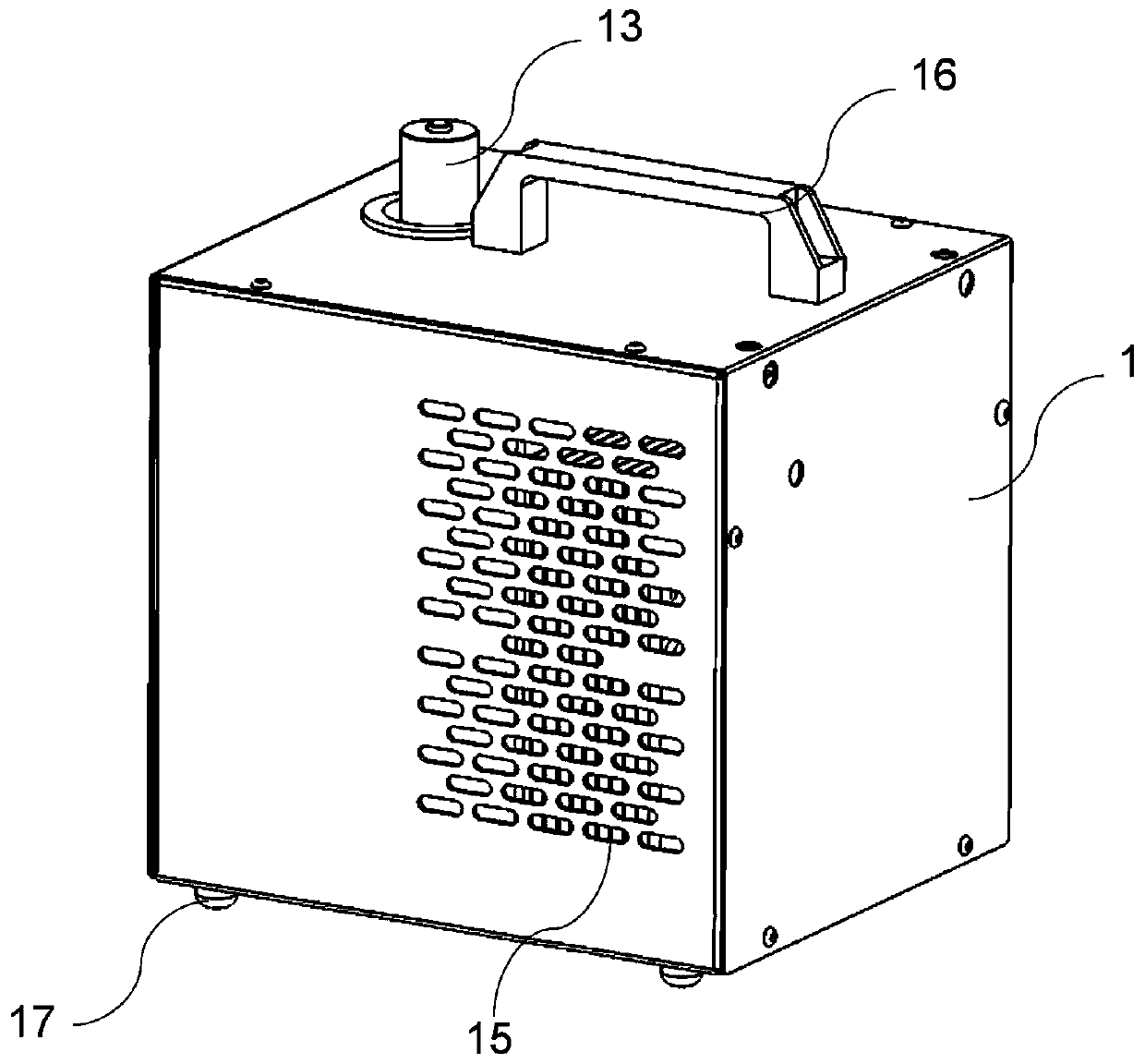
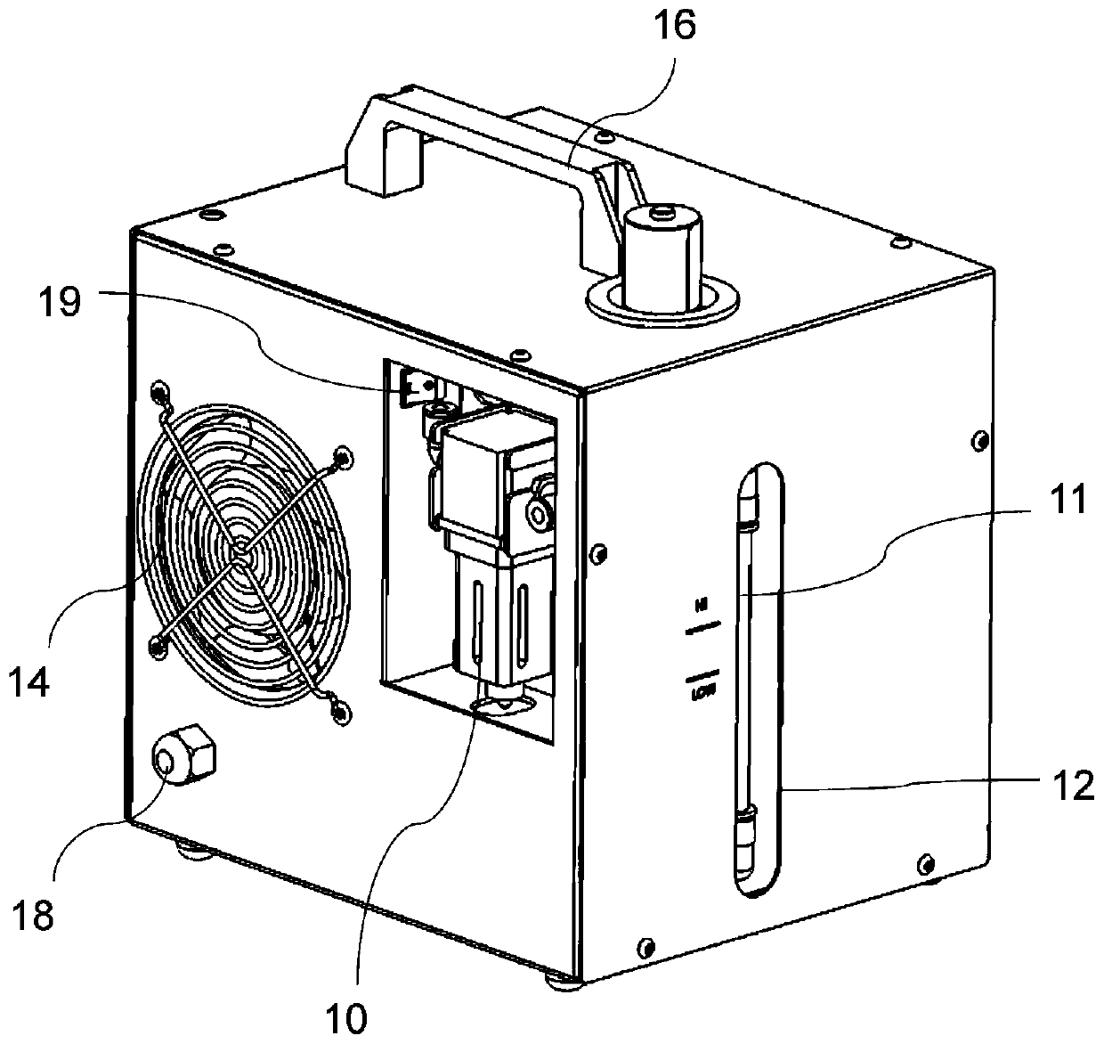
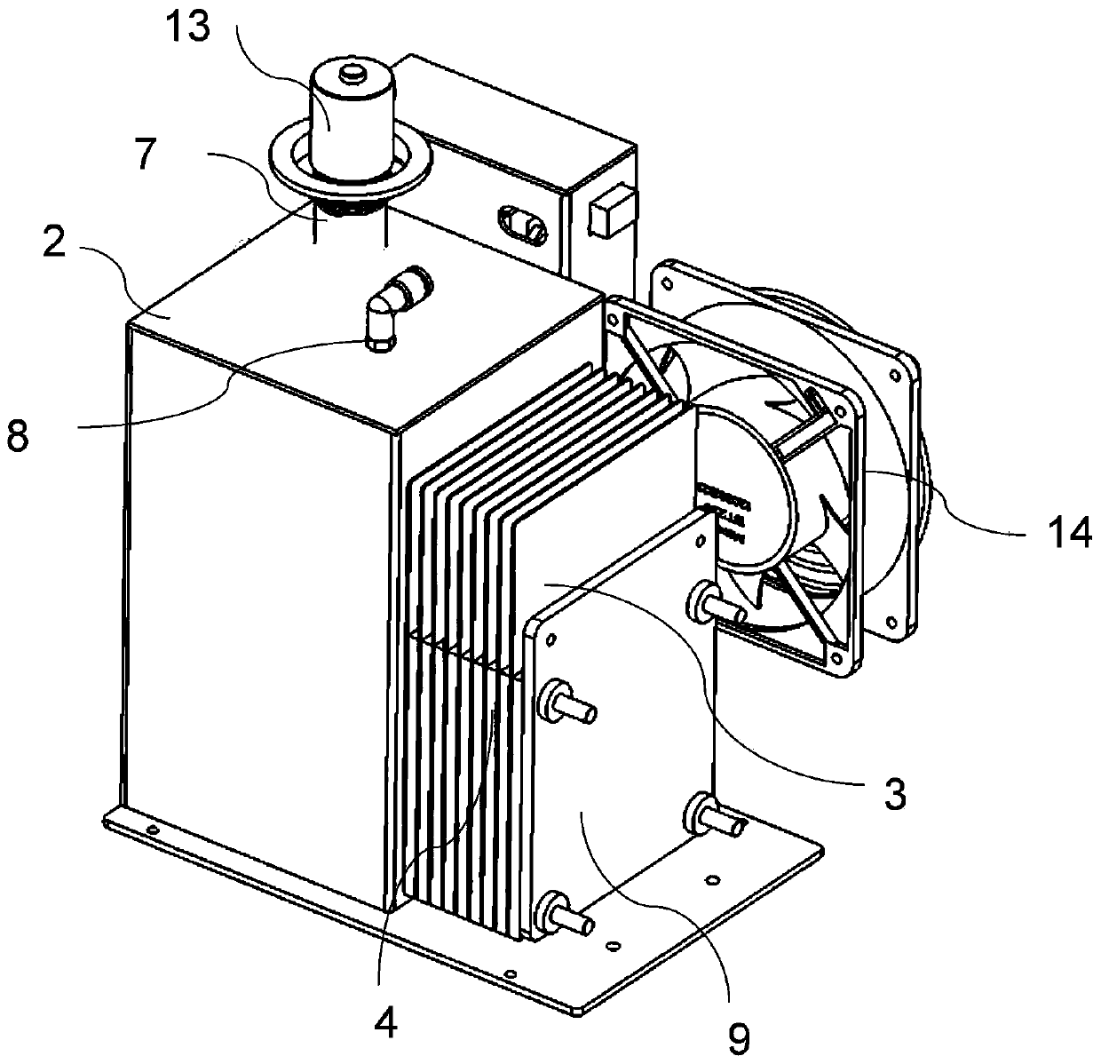
[0028] see Figure 1 to Figure 4 , a hydrogen-oxygen mixed gas generating device, including a box body 1 and a gas generation system arranged in the box body 1, the gas generation system includes a water tank 2 and several electrode plates 3 arranged close to one side of the water tank 2, preferably 5-15 pieces, considering the economy and electrolysis efficiency, the casing of the water tank 2 and the electrode plate 3 are preferably made of SUS stainless steel plates. The fixing piece 9 tightly fixes the above-mentioned electrode plates 3 on one side of the water tank 2 through bolts, and the interval between two adjacent electrode plates 3 is set between 1 and 10mm, and the total area of ​​5-15 electrode plates 3 is about 1000- 2000cm 2 , which can improve the hydrogen-oxygen gas production efficiency while taking into account the characteristics of portability and small volume. An insulator 4 is arranged between every two electrode plates 3, such as insulating rubber. On...


PUM


Abstract

The invention discloses a hydrogen-oxygen mixed gas generating device. The hydrogen-oxygen mixed gas generating device comprises a box and a gas generating system arranged in the box. The gas generating system comprises a water tank and a plurality of electrode plates arranged attached to one side face of the water tank. An insulator is arranged between every two electrode plates, and one side face of the water tank and the electrode plates are each provided with at least one gas circulating hole and at least one liquid circulating hole. The gas circulating holes of every two electrode platesare formed in a staggered manner, and the liquid circulating holes of every two adjacent electrode plates are formed in a staggered manner. The liquid circulating holes communicate with the water tankand the electrode plates to form electrolyte channels, and the gas circulating holes communicate with the water tank and the electrode plates to form oxygen channels. According to the hydrogen-oxygenmixed gas generating device, the combustion speed of fossil fuel can be increased, combustion of the fossil fuel is helped, and the emissions of nitric oxide, carbon dioxide and the like during combustion are effectively reduced.

Description

technical field [0001] The invention relates to the technical field of hydrogen-oxygen electrolysis, in particular to a hydrogen-oxygen mixed gas generator. Background technique [0002] With the rapid development of industrialization, automobiles have become an indispensable means of transportation in people's daily life. Along with the needs of transportation, automobiles need to consume a large amount of non-renewable gasoline during operation, and at the same time emit a lot of exhaust gas, nitrogen oxides (NOx ) and carbon dioxide (CO2) emissions have increased, causing great environmental pollution and continuous warming of the environment. Environmental protection has become a major problem that countries need to solve urgently. Automobiles burn fossil fuels, such as fuel oil as the driving power of automobiles, but insufficient combustion of fossil fuels will produce a large amount of exhaust gas and particles, seriously polluting the atmospheric environment, and it ...

Claims


Application Information

Patent Timeline
Patent Type & Authority Applications(China)
IPC IPC(8): F02M25/12C25B1/06C25B9/06C25B15/00C25B9/17
CPCF02M25/12C25B15/00C25B1/04C25B11/00C25B9/17Y02E60/36Y02T10/12
Inventor 徐石姣梅世安
Owner 广州市爱科铼富新能源科技有限公司
Learn More