Eureka AIR delivers breakthrough ideas for toughest innovation challenges, trusted by R&D personnel around the world.

Ignition timing control system for internal combustion engine

a technology of ignition timing and control system, which is applied in the direction of electrical control, process and machine control, etc., can solve the problems of lowering drivability and not being able to properly set the ignition timing, and achieves improved drivability, higher diffusion speed, and stable combustion

Inactive Publication Date: 2010-10-28
HONDA MOTOR CO LTD
View PDF2 Cites 17 Cited by
  • Summary
  • Abstract
  • Description
  • Claims
  • Application Information

AI Technical Summary

Benefits of technology

[0010]Further, the basic value of ignition timing set as above is corrected according to the detected air-fuel ratio of the air-fuel mixture, whereby the ignition timing is finally set. The diffusion speed of atomized mist of fuel injected into the cylinders and the combustion speed of the air-fuel mixture are different depending on the air-fuel ratio of the air-fuel mixture. For example, as the air-fuel ratio is richer, the diffusion speed of atomized mist is lower, so that the rich air-fuel mixture remains in the vicinity of the ignition device longer, and the combustion speed of the air-fuel mixture becomes higher. Therefore, by correcting the basic value of ignition timing according to the air-fuel ratio of the air-fuel mixture, it is possible to set the ignition timing in the compression stroke injection mode to more appropriate timing according to the difference in the diffusion speed of atomized mist of fuel and the difference in the combustion speed of the air-fuel mixture depending on the air-fuel ratio. As a result, it is possible to ensure stable combustion without causing a misfire or knocking, thereby making it possible to improve drivability.
[0012]With this configuration, the internal EGR amount parameter indicative of the internal EGR amount is acquired, and the ignition timing is further corrected according to the acquired internal EGR amount parameter. The diffusion speed of atomized mist of fuel injected into the cylinders is different depending on the internal EGR amount. For example, as the internal EGR amount is larger, the temperature of the air-fuel mixture is higher, which makes the diffusion speed higher. Therefore, by correcting the ignition timing according to the internal EGR amount parameter in addition to correcting the same according to the air-fuel ratio, it is possible to set the ignition timing in the compression stroke injection mode to the optimum timing also according to the difference of the diffusion speed of atomized mist of fuel depending on the internal EGR amount. This makes it possible to obtain more stable combustion and better drivability.

Problems solved by technology

However, in the conventional ignition timing control system, ignition timing for the stratified combustion is set according to only the engine speed and the basic fuel injection amount or the target engine torque, and hence it is not necessarily possible to properly set the ignition timing, depending on the operating conditions of the engine.
As a result, a misfire or knocking is caused, making it possible to obtain stable combustion, and hence there is a fear that drivability is lowered.

Method used


Image

  • Ignition timing control system for internal combustion engine
  • Ignition timing control system for internal combustion engine
  • Ignition timing control system for internal combustion engine

Examples


second embodiment

[0115]FIGS. 17 and 18 show the present invention. The second embodiment differs from the above-described first embodiment in the method of calculating the basic value IGBASE of ignition timing and the air-fuel ratio-dependent correction term ΔIGAF.

[0116]In the process for calculating the basic value IGBASE shown in FIG. 17, similarly to FIG. 11, it is determined whether or not the combustion mode transition flag F_DSCMD is equal to 0 (step 71), and whether or not the idle control flag F_IDLEFB is equal to 1 (step 72), respectively.

[0117]If the answers to the questions of the step 71 and 72 are both affirmative (YES), a map value IGIDLE2 is determined by searching a map (not shown) for the idle control according to the target idle speed NOBJ and the fuel injection timing INJOBJ, and is set as the basic value IGBASE (step 73), followed by terminating the present process.

[0118]If the answer to the question of the step 72 is negative (NO), i.e. if it is not during the idle control, the ...


PUM


Abstract

To provide an ignition timing control system for an internal combustion engine, which is capable of ensuring stable combustion without causing a misfire or knocking, by properly setting ignition timing in the compression stroke injection mode, thereby making it possible to improve drivability. The ignition timing control system for the engine 3 that directly injects fuel into cylinders 3a and is operated by switching the fuel injection mode between an intake stroke injection mode and a compression stroke injection mode comprises fuel injection timing-setting means 2 for setting a fuel injection timing INJOBJ according to an engine speed NE of the engine 3 and a fuel injection amount GFUEL, basic value-setting means 2 for setting a basic value IGBASE of ignition timing according to the engine speed NE of the engine 3 and the fuel injection timing INJOBJ, and ignition timing-setting means 2 for setting ignition timing IGCOMP in the compression stroke injection mode by correcting the basic value IGBASE according to a detected air-fuel ratio AF.

Description

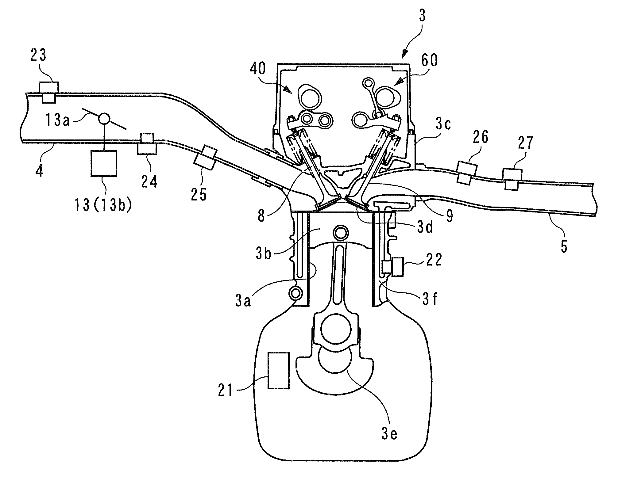
FIELD OF THE INVENTION[0001]The present invention relates to an ignition timing control system for an internal combustion engine which directly injects fuel into cylinders and is operated by switching the fuel injection mode between a suction stroke injection mode in which fuel is injected during the suction stroke and a compression stroke injection mode in which fuel is injected during the compression stroke, the ignition timing control system controlling ignition timing in the compression stroke injection mode.BACKGROUND ART[0002]Conventionally, as an ignition timing control system for an engine, one disclosed in Patent Literature 1 is known. This engine is of a direct fuel-injection type which is configured to directly inject fuel into cylinders, and in the engine, homogeneous combustion in which fuel is injected during the suction stroke and a homogeneous air-fuel mixture generated in a combustion chamber is burned and stratified combustion in which fuel is injected during the c...

Claims


Application Information

Patent Timeline
IPC IPC(8): F02D41/00
CPCF02D13/0246F02D13/0249F02D37/02F02D41/0062F02D41/1454Y02T10/18F02M25/0752F02P5/1502Y02T10/46Y02T10/47F02D41/3029F02M26/01Y02T10/12Y02T10/40
Inventor ITOGA, CHIHOKITAMURA, TORUSHINOHARA, TOSHINARI
Owner HONDA MOTOR CO LTD
Why Eureka
Eureka Blog
Learn More