Efficient spiral tube heat exchanger

A technology of spiral heat exchange tubes and spiral tubes, applied in the direction of heat exchanger types, heat exchanger shells, indirect heat exchangers, etc., can solve problems such as large installation space, large installation space, and complex pipeline structure

Active Publication Date: 2020-02-11
LANZHOU UNIVERSITY OF TECHNOLOGY
View PDF6 Cites 0 Cited by
  • Summary
  • Abstract
  • Description
  • Claims
  • Application Information

AI Technical Summary

Problems solved by technology

However, the installation space occupied by pipelines arranged side by side is relatively large, which is contrary to the design idea of ​​saving space; during the process of fluid transmission, especially the vibration of pipelines caused by high-speed fluid transmission, it will cause the vibration of adjacent pipelines. Friction and collision, when the pipeline is long, the diameter is small, and the stiffness is low, the vibration phenomenon is more obvious, which will seriously affect the safety and stability of the pipeline
If anti-vibration equipment is installed to increase the pipe clearance, not only will it require a larger installation space, but it will also make the pipeline structure more complicated and increase the cost of installation and maintenance

Method used


Image

  • Efficient spiral tube heat exchanger
  • Efficient spiral tube heat exchanger
  • Efficient spiral tube heat exchanger

Examples


Embodiment Construction

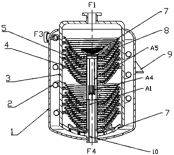
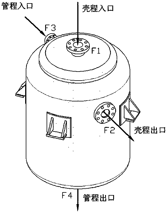
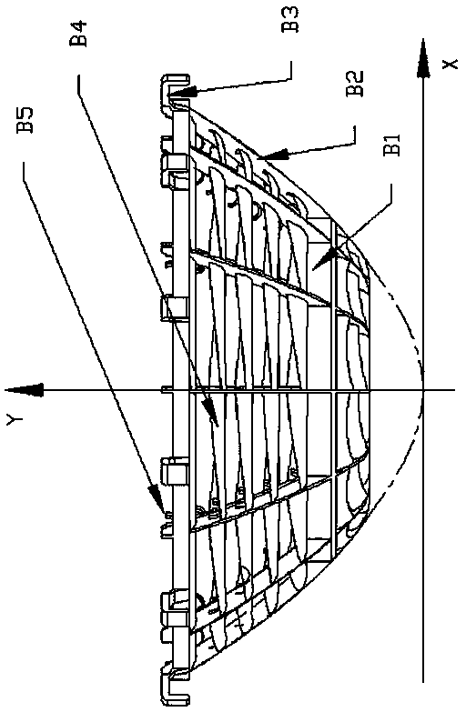
[0007] The present invention is a high-efficiency spiral tube heat exchanger, such as Figure 1~Figure 10 As shown, it includes an outer shell 1 and an inner shell 3, a spiral surrounding inlet pipe 2 is placed in the interlayer between the two shells, and a parabolic distribution spiral heat exchange tube 5 is superimposed and placed inside the inner shell 3, which is located in the inner shell 3. The main outer tube A3 at the central position is connected, and the parabolic distribution spiral heat exchange tube 5 is supported by the parabolic flow guide support frame 4, and the inner shell support frame 6 is supported on the bottom of the outer shell 1 at the bottom of the inner shell 3 and kept in contact with the outer shell 1 There is a preset distance between the heads, the heat exchange pipe flow diversion device 10 is fixed on the support frame 6 of the inner shell, and the upper top of the main outer pipe A3 is equipped with a reverse flow plug 8, and the top of the r...


PUM


Abstract

The invention provides an efficient spiral tube heat exchanger. A paraboloid distribution spiral heat exchange tube (5) is stacked in an inner shell (3) and is connected with a main outer tube (A3) inthe center, the paraboloid distribution spiral heat exchange tube (5) is supported by a paraboloid flow guide support (4), the bottom of the inner shell (3) is provided with an inner shell support (6) which is supported at the bottom of an outer shell (1), a heat exchange pipeline flow dividing device (10) is fixed to the inner shell support (6), a backflow plug (8) is installed at the top end ofthe main outer tube (A3), and a flow stabilizing distribution cover (7) is installed above the backflow plug (8). The paraboloid flow guide support (4) mainly comprises annular ribbed plates (B1) andparaboloid longitudinal ribbed plates (B2), fixing clamping hooks (B3) are evenly distributed on the upper side of the uppermost annular ribbed plate (B1) in circumferential direction, anti-gravity flow guide blades (B4) are distributed between the paraboloid longitudinal ribbed plates (B2), and spiral tube heat exchange tube buckles (B5) are distributed on the inner sides of the paraboloid longitudinal ribbed plates (B2).

Description

technical field [0001] The invention relates to the technology of spiral tube heat exchanger. Background technique [0002] In the prior art, due to its flow characteristics, the spiral tube heat exchanger has a relatively low logarithmic mean temperature difference with a large heat transfer area no matter in the downstream or countercurrent conditions. Inhomogeneity, the flow velocity at the center of the inlet inside the shell side is much higher than the flow velocity at the edge. In addition, due to the decrease in the heat exchange temperature difference at the end of the heat exchange, the overall heat exchange efficiency is significantly reduced; in order to increase the convection of the spiral tube heat exchanger Thermal coefficient, the existing method usually adds a built-in spiral belt in the heat exchange tube in the spiral tube heat exchanger, and the heat exchange tube is equipped with baffles or false tubes and other spoiler components, although the convecti...

Claims


Application Information

Patent Timeline
Patent Type & Authority Applications(China)
IPC IPC(8): F28D7/02F28F9/22
CPCF28D7/022F28F9/22
Inventor 余龙俞树荣张剑
Owner LANZHOU UNIVERSITY OF TECHNOLOGY
Why Eureka
Try Eureka