Pressure-regulating type perfusion plugging machine

A pressure-regulating and leaking machine technology, which is applied in building maintenance, construction, building construction, etc., can solve structural compressive strength and shear force changes, concrete structure damage, and difficult cleaning, etc., to reduce hazards , avoid waste, reduce the effect of cleaning difficulty

Inactive Publication Date: 2020-02-11
湖南古圣砖瓦科技有限公司
View PDF6 Cites 2 Cited by
  • Summary
  • Abstract
  • Description
  • Claims
  • Application Information

AI Technical Summary

Problems solved by technology

[0003] One, as attached Figure 4 As shown, the high-pressure grouting plugging machine uses the gear set 2, the hand-held motor 3 and the cam turntable 4 to drive, so that the connecting rod 5 drives the movable pull rod 6 to move in parallel, and makes the piston rod 7 move in the piston copper sleeve 8 at a fixed distance. , to push out the slurry dropped from the barrel 9, forming a certain high pressure in a short time and injecting it into the crack. However, the compressive strength and shearing force of concrete structures of different buildings are different. The size and shape will also lead to changes in the compressive strength and shear force of the structure. If high-pressure grouting is used blindly to plug leaks, once the grouting pressure exceeds the shear strength of the defect in the concrete structure, not only the purpose of repair cannot be achieved, but also may cause damage to the concrete structure
[0004] Its two, because the switch control of hand-held motor 3 and the location of one-way switch 14 are no longer in the same position, often in the running process, once plugging is completed, at first close the switch of one-way switch 14 and then close the hand-held motor 3, and hand-held motor 3 It will still run for a period of time after it is closed, which will easily cause the slurry to continue to be discharged, causing the slurry to form a local high pressure in the delivery pipe 12, resulting in a large number of internal blockages, difficult to clean, and waste of slurry

Method used


Image

  • Pressure-regulating type perfusion plugging machine
  • Pressure-regulating type perfusion plugging machine
  • Pressure-regulating type perfusion plugging machine

Examples


Embodiment Construction

[0020] The following will clearly and completely describe the technical solutions in the embodiments of the present invention with reference to the accompanying drawings in the embodiments of the present invention. Obviously, the described embodiments are only some, not all, embodiments of the present invention. Based on the embodiments of the present invention, all other embodiments obtained by persons of ordinary skill in the art without making creative efforts belong to the protection scope of the present invention.

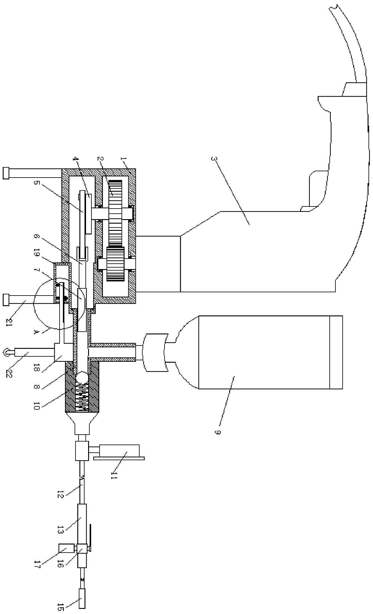
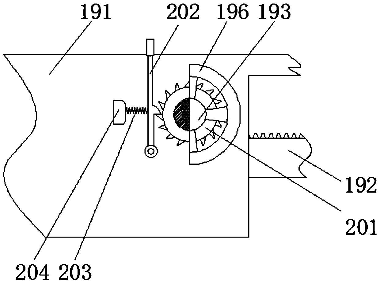
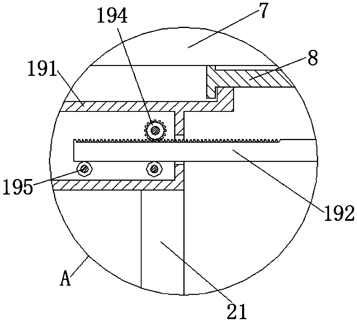
[0021] see Figure 1-3 , a pressure-regulating perfusion plugging machine, including a gearbox 1, a gear set 2, a hand-held motor 3, a cam turntable 4, a connecting rod 5, a movable pull rod 6, a piston rod 7, a copper piston sleeve 8, a barrel 9, a stopper return device 10, pressure gauge 11, conveying pipe 12, metal pipe 13, butter head 15, two-way switch 16, receiving bottle 17, fixed seat 18, regulating device 19, limiting device 20, supporting leg 21 and ...


PUM


Abstract

The invention relates to the technical field of construction machinery, and discloses a pressure-regulating type perfusion plugging machine. The pressure-regulating type perfusion plugging machine comprises a gearbox, a gear set, a hand-held motor, a cam rotating disc, a connecting rod, a movable pull rod, a piston rod, a piston copper sleeve, a material cylinder, a check-back device, a pressure gauge, a conveying pipe, a metal pipe, an avocado head, a bidirectional switch, a material receiving bottle, a fixing seat, an adjusting device, a limiting device, a supporting leg and a movable leg, wherein the gear set is movably installed inside the gearbox. According to the pressure-regulating type perfusion plugging machine, through the arrangement of the adjusting device, the effective movable distance of the piston rod in the piston copper sleeve is changed, so that the size of slurry discharged from the piston rod during one time of reciprocation is changed, the slurry discharging pressure is further changed, the adaptability for cracks on different buildings and cracks of different positions and sizes can be effectively improved, and the adaptation range of the machine is increased; and meanwhile, suitable slurry pressure can effectively improve the safety of building crack filling, and the harm caused by excessive pressure can be reduced.

Description

technical field [0001] The invention relates to the technical field of construction machinery, in particular to a pressure regulating type perfusion plugging machine. Background technique [0002] High-pressure grouting plugging technology is a new technology of high-pressure airless grouting waterproofing with international advanced level. The high-pressure grouting plugging machine uses the high-pressure power of machinery to inject water-soluble or oil-soluble polyurethane chemical grouting materials into concrete cracks. When the grout meets Moisture in concrete cracks will quickly disperse, emulsify, expand, and consolidate Oil-soluble polyurethane will expand and consolidate without water, so that the consolidated elastomer fills all cracks in concrete and completely blocks water flow between concrete structures In addition, in order to achieve the purpose of water stop and leak plugging, but there are some shortcomings in the use of this equipment, as follows: [000...

Claims


Application Information

Patent Timeline
Patent Type & Authority Applications(China)
IPC IPC(8): E04G23/02
CPCE04G23/0203
Inventor 崔州赵忠荣杨水云钟华艳
Owner 湖南古圣砖瓦科技有限公司
Why Eureka
Try Eureka