
Cathode material

A cathode material and emitter technology, which is applied in the manufacture of thermionic cathodes, electrical components, discharge lamps, etc., can solve the problems of uneven distribution of emitter materials and unstable arc, and achieve stable shape, less evaporation, and low blackness. Effect

Active Publication Date: 2020-02-04
PLANSEE SE +1
View PDF4 Cites 1 Cited by
  • Summary
  • Abstract
  • Description
  • Claims
  • Application Information

AI Technical Summary

Problems solved by technology

The resulting uneven distribution of emitter material can also lead to arc instability

Method used


Image

  • Cathode material
  • Cathode material
  • Cathode material

Examples


Embodiment Construction

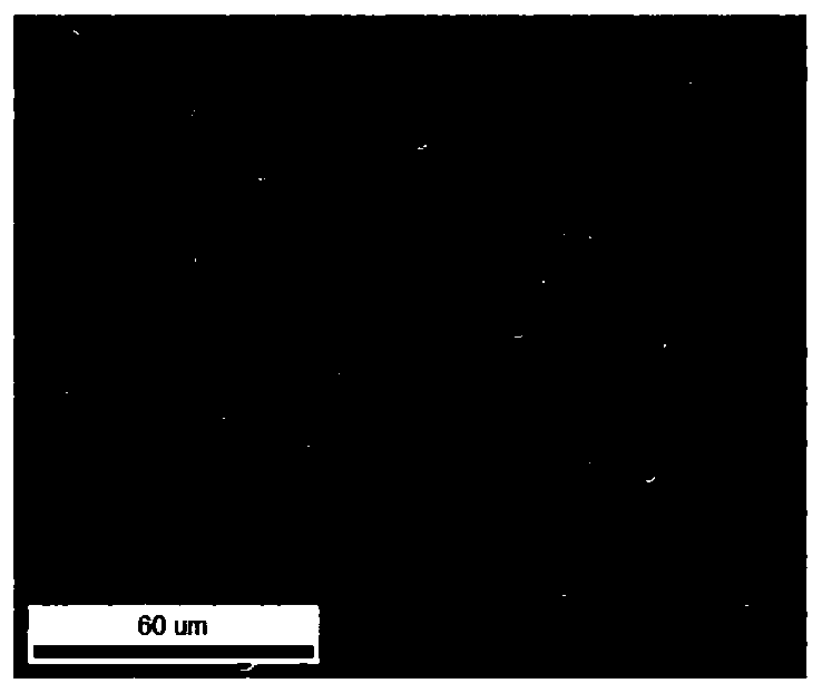
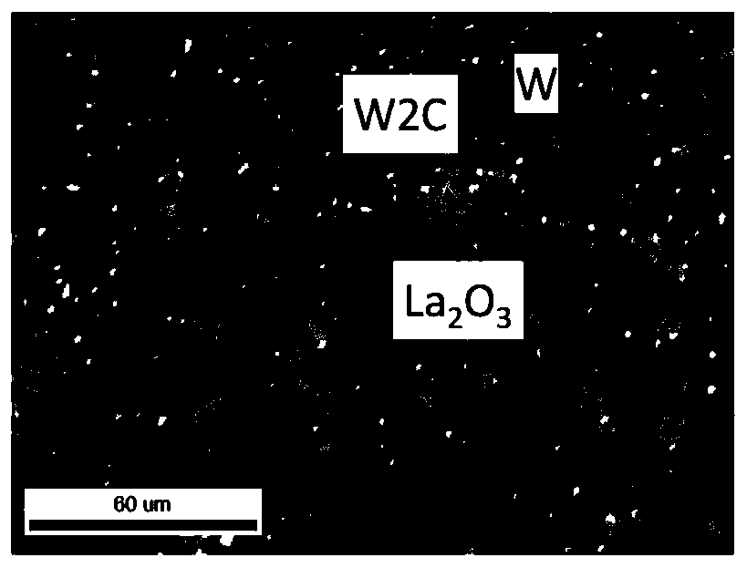
[0078] Figure 1a Containing W, 2% by weight La is shown 2 o 3 and 800 μg / g C cathode material secondary electron scanning electron microscope (SEM). Figure 1b The phase diagram corresponding to electron backscatter diffraction (EBSD) is shown.

[0079] Lanthanum is therefore chosen as the emitter element in this embodiment of the cathode material. Figure 1b The dark gray phase in is the tungsten matrix, and the light gray phase is W 2 C, the white phase is La 2 o 3 .

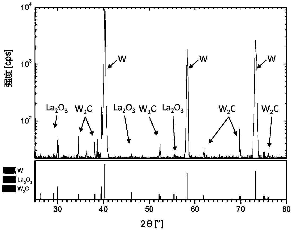
[0080] It can be seen that most of the lanthanum oxide particles are removed in preparation for the EBSD method. The phase diagram shows that the material not only consists of a W (tungsten) matrix and lanthanum oxide particles, but also at least a carbide phase (W 2 C) Composition.

[0081] According to the analysis of 5 images, W 2 The average area ratio of the C phase was 0.5%. Assuming no preferred orientation of the grains, the volume ratio is equal to the area ratio. The area ratio is 0.5% of...


PUM

PropertyMeasurementUnit
thicknessaaaaaaaaaa
densityaaaaaaaaaa

Abstract

The invention relates to a cathode material for use in a high intensity discharge lamp, said material containing at least the following elements: a matrix based on tungsten having a tungsten content of more than or equal to 95 wt.%; tungsten carbide; oxides and or predominantly oxidic phases of one or more emitter elements from the group consisting of (rare earth metals, Hf Zr), wherein the cathode material contains predominantly carbide phases from one or more emitter elements from the group (rare earth metals, Hr, Zr). The invention relates to a high intensity discharge lamp which comprisesa cathode made from the claimed cathode material and to a method for producing a cathode material.

Description

technical field [0001] The invention relates to a cathode material for a high-pressure discharge lamp having the features of the preamble of claim 1 . The invention also relates to a high-pressure discharge lamp comprising a cathode composed of the cathode material according to the invention and a method for producing the cathode material. Background technique [0002] The task of the cathode of a high-pressure discharge lamp is to supply electrons at a sufficient current density. At the typical current densities of high-pressure discharge lamps, this can only be achieved at sufficiently high cathode temperatures, so especially tungsten-based materials are recognized here due to their high melting points. [0003] High-pressure discharge lamps often fail or degrade due to changes in the morphology, structure and shape of the cathode as well as increases and / or local changes in the electronic work function during use of the cathode material. One or more of the following eff...

Claims


Application Information

Patent Timeline
Patent Type & Authority Applications(China)
IPC IPC(8): H01J9/04H01J61/073
CPCH01J9/04H01J61/0735C22C1/051
Inventor 汉尼斯·特拉克斯勒英格玛·韦斯曼沃尔夫拉姆·克纳布亚历山大·泰罗曼玛丽娜·尼利斯
Owner PLANSEE SE
Learn More