A compact flangeless waveguide connection structure and design method

A connection structure without flange technology, applied in the microwave field, can solve the problems of low mechanical stability of the direct butt welding structure, which is not conducive to the overall design and flexible layout of the system, and the electromagnetic transmission performance is difficult to predict and guarantee. Miniaturization and flexible layout, reliable electromagnetic transmission performance, and the effect of avoiding electromagnetic leakage

Active Publication Date: 2022-02-01
XIAN INSTITUE OF SPACE RADIO TECH
View PDF5 Cites 0 Cited by
  • Summary
  • Abstract
  • Description
  • Claims
  • Application Information

AI Technical Summary

Problems solved by technology

If the consistency of the welding process is difficult to ensure, the electromagnetic transmission performance of the welded flangeless waveguide connection is difficult to predict and guarantee
On the other hand, welding is an irreversible process. Once the welding is completed, the structure and position of the waveguide cannot be changed, which is not conducive to the flexible disassembly and assembly of various components and components in the system, and is not conducive to the overall design and flexible layout of the system. low mechanical stability
If the waveguide direct plug-in design is adopted, due to the existence of machining errors and roughness, ideal electrical contact cannot be formed in practice, and there will be air gaps between the plug-in contact surfaces, causing electromagnetic leakage and affecting electromagnetic transmission performance

Method used


Image

  • A compact flangeless waveguide connection structure and design method
  • A compact flangeless waveguide connection structure and design method
  • A compact flangeless waveguide connection structure and design method

Examples


Embodiment

[0066] Taking the realization of the compact flangeless connection of the Ku-band BJ120 (WR75) waveguide (working bandwidth 9.84GHz to 15GHz) as an example, the specific implementation process of the present invention will be described:

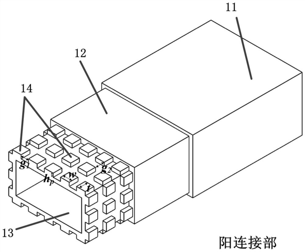
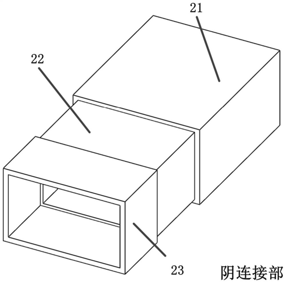
[0067] (1) Determine the structural dimensions of the first impedance transformation section 12, the first non-standard waveguide section 13 and the second impedance transformation section 22 by the stepped impedance transformation method. Here, the first-order stepped impedance transformation method is selected, and the electrical simulation is performed by an electromagnetic simulation program. Transmission performance, working bandwidth covers the entire BJ120 waveguide working bandwidth.

[0068] (2) In the electromagnetic simulation program, a simulation model of a single metal convex body in the periodic metal convex body array 14 is established, such as: Figure 5 As shown, the height of each metal protrusion in the periodic metal prot...


PUM


Abstract

The invention discloses a compact flangeless waveguide connection structure. The male connection part includes a first standard waveguide, a first impedance transformation section, a first non-standard waveguide section and a periodic metal convex array, wherein the first impedance transformation section is located at Between the first standard waveguide and the first non-standard waveguide section, a periodic array of metal protrusions is arranged around the outer wall of the first non-standard waveguide section, and several metal protrusions are evenly arranged in a periodic layout rule; the female connection part includes the first non-standard waveguide section. Two standard waveguides, a second impedance transformation section and an enlarged cavity structure, the second impedance transformation section is located between the second standard waveguide and the enlarged cavity structure, and the enlarged cavity structure is arranged at the end of the second impedance transformation section; the male connection part One end with a periodic metal convex array is inserted into the enlarged cavity structure of the female connection part to form a compact flangeless waveguide connection structure as a whole. The volume of the invention is greatly reduced, which is more conducive to miniaturization design and flexible layout, and the plug-in design can realize more convenient and flexible assembly.

Description

technical field [0001] The invention relates to a compact blue-free waveguide connection structure and a design method, which can be used in various microwave components and system connection structures, and belongs to the microwave technical field. Background technique [0002] Waveguide is an important transmission line for transmitting microwave signals. The most commonly used is a rectangular waveguide, including a rectangular metal tube and a flange. The flanges are located at both ends of the metal tube and are used for connection and fixation between the waveguides. The metal tube and the flange surface Vertical and centered, the rectangular section and flange surface of the waveguide in different frequency bands are different in size. Waveguide transmission lines are widely used in satellite payload systems due to their advantages of low insertion loss and high power capacity. Due to the limitation of the space of the satellite payload platform and the carrying capa...

Claims


Application Information

Patent Timeline
Patent Type & Authority Patents(China)
IPC IPC(8): H01P1/04H01P11/00G06F30/20G06F111/10
CPCH01P1/042H01P11/00
Inventor 陈翔孙冬全李小军崔万照殷康贺永宁
Owner XIAN INSTITUE OF SPACE RADIO TECH
Why Eureka
Try Eureka