A three -phase voltage harmonic synchronous detection method

A technology of high-voltage transmission lines and three-phase voltage, applied in the direction of measuring current/voltage, measuring only voltage, voltage divider, etc., can solve the problems of inaccurate measurement results, deviation of measurement results, non-linear proportional relationship, etc., and achieve the detection process Simple and convenient, improve the detection accuracy and ensure the effect of synchronization

Active Publication Date: 2022-05-17
QUANZHOU POWER SUPPLY COMPANY OF STATE GRID FUJIAN ELECTRIC POWER +1
View PDF11 Cites 0 Cited by
  • Summary
  • Abstract
  • Description
  • Claims
  • Application Information

AI Technical Summary

Problems solved by technology

However, due to the inherent influence of CVT transmission characteristics, this method is not suitable for harmonic analysis. The national standard GB / T14549 "Power Quality Harmonics of Public Grid" and IEC related standards clearly stipulate that CVT cannot be used for harmonic measurement.
The reason is that by measuring the harmonic content of the secondary voltage signal of the CVT, and then converting the harmonic content of the line according to the ratio, this measurement method will attenuate the harmonics of different frequencies in different proportions due to the capacitance characteristics of the CVT itself, and the attenuation ratio does not vary. The non-linear proportional relationship leads to a large deviation in the measurement results, and the maximum deviation can reach 36.70%. Therefore, the harmonic voltage test results measured from the CVT will cause false phenomena that the power supply voltage of many public connection points is unqualified.
Therefore, the traditional CVT detection of high-voltage line harmonics is not accurate enough, and the traditional detection method can only measure the internal lines of the substation. For the high-voltage lines outside the substation, the harmonics cannot be measured because there is no CVT cabinet installed.
At the same time, for the 10kV high-voltage line, since the neutral point of the primary side of the CVT is grounded with a harmonic elimination resistor in series, it may affect the measurement results of the harmonic voltage that reflects the zero-sequence characteristics (such as the third harmonic), and finally affect the harmonic voltage. The test result of the total distortion rate

Method used


Image

  • A three -phase voltage harmonic synchronous detection method
  • A three -phase voltage harmonic synchronous detection method
  • A three -phase voltage harmonic synchronous detection method

Examples


Embodiment 1

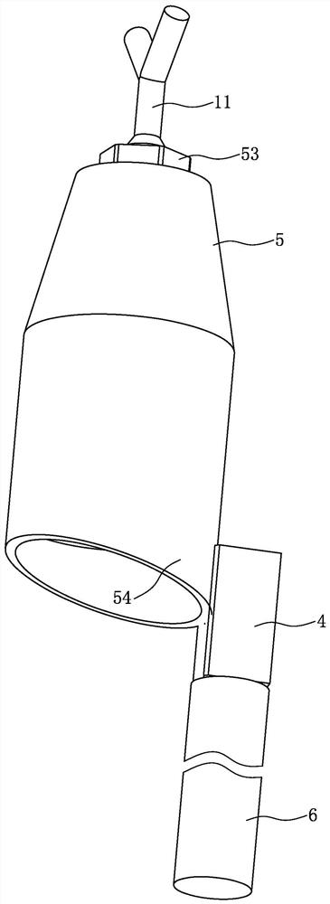
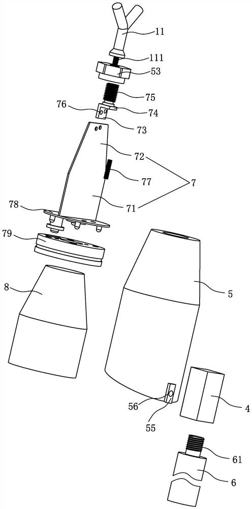
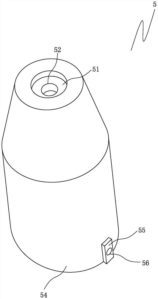
[0032] Such as Figure 1 to Figure 6As shown, the high-voltage transmission line harmonic detection system includes three insulated telescopic rods 6, three detection devices 1 respectively arranged on the three insulated telescopic rods 6, a wireless communication device 2, and a handheld Device 3, the handheld device 3 is arranged at the far end, and the detection device 1 includes a PCB board, metal electrodes 11 respectively arranged on the PCB board, a voltage dividing capacitor 12, an air-core inductor L, a resistor R1, a high-voltage discharge tube R2, a diode D1, RC filter circuit, signal processing unit and sound and light prompt unit, metal pressure equalizing cover 8 covering the PCB board and insulating shell 5 arranged on the outer periphery of the metal pressure equalizing cover 8, the PCB board ground layer is coated with copper, and the signal processing unit includes input terminals and The follower amplifier 13 that the pressure dividing capacitor 12 is conne...

Embodiment 2

[0047]The difference between this embodiment and Embodiment 1 is that the signal processing unit includes a follower amplifier whose input end is connected to the voltage dividing capacitor, a first microprocessor whose input end is connected to the output end of the follower amplifier, and the handheld device includes a second microprocessor, The key unit is connected with the input end of the second microprocessor and the display unit is connected with the output end of the second microprocessor, and the first microprocessor and the second microprocessor are connected through wireless two-way communication through a wireless communication device. The voltage at both ends of the voltage dividing capacitor is directly analyzed by the first microprocessor, and due to the limitation of the FFT calculation capability of the first microprocessor, it can only process FFT with a limited number of points, so when intercepting the periodic signal in the time domain, Integer multiple cy...

Embodiment 3

[0049] Such as Figure 7 As shown, the difference between this embodiment and Embodiment 1 is that the transmission line harmonic detection device has a self-power supply unit, specifically: the detection device includes a first PCB board, a second PCB board, metal electrodes, a voltage dividing capacitor, and a signal processing unit The same as the self-power supply unit, the signal processing unit is the same as the first embodiment, the first PCB board is arranged horizontally and the ground layer is covered with copper, the second PCB board is vertically welded on the first PCB board, and the metal electrodes are arranged on the top of the second PCB board to divide the voltage. The capacitor, the signal processing unit and the self-power supply unit are arranged on the second PCB board, and the metal electrodes are connected in series with the voltage dividing capacitor. The self-power supply unit includes a rectification circuit, an electric energy chip IC3 and an energy...


PUM


Abstract

The invention provides a method for synchronous detection of three-phase voltage harmonics of a high-voltage transmission line, which includes the following steps: respectively bringing three detection devices close to or in contact with the high-voltage transmission line, and connecting the first and second stray capacitances formed with the voltage-dividing capacitance in series ; Send the ASK-modulated 50Hz square wave signal to the three signal processing units through the remote handheld device to make them open synchronously, and each signal processing unit starts to collect the voltage at both ends of the voltage dividing capacitor after receiving the square wave signal, and After calculating the harmonic content of the transmission line voltage based on this voltage, the calculation result is sent to the handheld device. The invention utilizes the electric field coupling to realize the direct synchronous detection of the harmonic content of the three-phase high-voltage transmission line, the detection is simple and convenient, the precision is high, the voltage level of the voltage transmission line is not limited, and the application range is wide.

Description

technical field [0001] The invention relates to the field of harmonic detection, in particular to a method for synchronous detection of three-phase voltage harmonics of a high-voltage transmission line. Background technique [0002] The traditional harmonic detection method for high-voltage transmission lines adopts a wired method, that is, the harmonic detector is connected to the secondary side of the PT / CVT in the substation, and the voltage on the bus is detected by detecting the small voltage signal at the secondary end of the PT / CVT. Obtain the harmonic content in transmission lines. According to statistics, almost all voltage transformers with a voltage level above 72.5kV in foreign countries use capacitive voltage transformers (CVT). In China, CVTs are also widely used in voltage transformers with voltage levels above 110kV. However, due to the inherent influence of CVT transmission characteristics, this method is not suitable for harmonic analysis. The national sta...

Claims


Application Information

Patent Timeline
Patent Type & Authority Patents(China)
IPC IPC(8): G01R19/00G01R23/167G01R15/06G01R1/04
CPCG01R19/0084G01R23/167G01R15/06G01R1/04
Inventor 杨文陵连和沈谢林伍长志陈静颖赵欢陈龙毅叶开发曾玮强林涌艺
Owner QUANZHOU POWER SUPPLY COMPANY OF STATE GRID FUJIAN ELECTRIC POWER
Why Eureka
Try Eureka