
Energy-absorbing automobile engine suspension

A technology for engine mounts and automobile engines, which is applied in power units, mechanical equipment, vehicle components, etc., can solve the problems of high natural vibration frequency, poor integrity, and cannot meet the requirements of vibration reduction and noise reduction, so as to reduce the occupation. Space and easy disassembly

Pending Publication Date: 2020-01-21
詹勋
View PDF0 Cites 2 Cited by
  • Summary
  • Abstract
  • Description
  • Claims
  • Application Information

AI Technical Summary

Problems solved by technology

[0005] The purpose of the present invention is to provide an energy-absorbing engine mount with better vibration isolation effect to solve the problem that the existing mount cannot meet the requirements of vibration and noise reduction on the wide frequency band under the multi-working conditions of the automobile; to solve the problem of the existing mount Poor vibration damping effect, high natural vibration frequency, unstable and unreliable work; at the same time, it also solves the disadvantages of weak integrity between the various support points of the engine

Method used


Image

  • Energy-absorbing automobile engine suspension
  • Energy-absorbing automobile engine suspension
  • Energy-absorbing automobile engine suspension

Examples


Embodiment Construction

[0056] The present invention will be described in detail below in conjunction with specific embodiments and accompanying drawings.

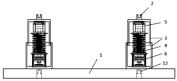
[0057] Said energy-absorbing engine mount, one end is fixedly connected to the engine damping block 1 on the chassis of the automobile through the installation buckle 2, and the other end is fixedly connected to the automobile engine through the installation buckle 12, and the mount includes the installation buckle 2 , mounting buckle 12, shell 3, spiral wire rope shock absorber 4, hydraulic damper 5 and magnetorheological damper 6, etc., said shell 3 includes upper and lower shells, non-contact installation, to ensure that the engine suspension moves up and down There is no interference in the process.

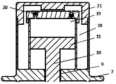
[0058] The spiral wire rope shock absorber 4 includes a limit plate one 7, a limit plate two 8, an annular ventilation duct 9, a spiral steel wire rope 17, a guide rod one 10, and a guide rod two 11. Described limiting plate one 7 and limiting ...


PUM


Abstract

The invention discloses an energy-absorbing automobile engine suspension. One end of the energy-absorbing automobile engine suspension is fixedly connected to the engine damping block on an automobilechassis through a mounting buckle, and the other end of the energy-absorbing automobile engine suspension is fixedly connected to an automobile engine through a mounting buckle. The energy-absorbingautomobile engine suspension comprises the mounting buckles, a shell, a spiral steel wire rope damper, a hydraulic damper and a magneto-rheological damper, the magneto-rheological damper further comprises a piston, a high magnetizer, an exciter coil, an annular magnet and a resistive ring and the like, the hydraulic damper further comprises a hydraulic cylinder, an oil storage tank and a damping control valve and the like, and the spiral steel wire rope damper further comprises a limiting plate, a spiral steel wire rope and a guiding rod and the like. Compared with a traditional hydraulic suspension, the energy-absorbing automobile engine suspension further has the advantage of active suspension, and self damping and stiffness can be changed according to the engine vibration changes so asto meet damping and noise reduction requirements of an automobile under the multiple conditions of the wide broadband as the energy-absorbing automobile engine suspension ingeniously connects the spiral steel wire rope damper, the hydraulic damper and the magneto-rheological damper in parallel to form an active suspension system.

Description

technical field [0001] The invention relates to an automobile engine suspension assembly, which is used to prevent the vibration of the automobile engine from being transmitted to the vehicle frame, and belongs to the field of automobiles. Background technique [0002] With the development of the economy and the continuous improvement of the road traffic environment, as well as the increasingly prominent problems of energy and pollution, the design of the car is developing in the direction of high torque and light weight, which greatly deteriorates the vibration characteristics of the car and seriously affect the ride comfort of the vehicle. A large number of studies and experiments have shown that the vibration of the automobile engine is one of the important factors that affect the ride comfort and handling stability of the automobile, as well as the fatigue life of automobile parts. Excessive vibration will accelerate the fatigue damage of parts and reduce the working li...

Claims


Application Information

Patent Timeline
IPC IPC(8): F16F13/00F16F9/53F16F9/34B60K5/12
CPCF16F13/007F16F9/535F16F9/34B60K5/12F16F2230/0052F16F2230/10
Inventor 詹勋万寿祥何功李子琦张金龙吴胜陈韵殷宝连昌海健
Owner 詹勋
Learn More