
Thermal control coating of spacecraft thermal shield sunward side

A thermal control coating and spacecraft technology, applied in the field of near-term detectors, can solve the problems of thermal control coatings with weak radiation and heat dissipation capabilities, and no special design for spectral emissivity, so as to improve thermal protection capabilities, reduce temperatures, and prolong service life The effect of longevity

Active Publication Date: 2020-01-17
YUNNAN ASTRONOMICAL OBSERVATORY CHINESE ACAD OF SCI
View PDF7 Cites 0 Cited by
  • Summary
  • Abstract
  • Description
  • Claims
  • Application Information

AI Technical Summary

Problems solved by technology

However, the thermal control coating of Parker Solar Probe has no special design for the spectral emissivity near the wavelength corresponding to the maximum thermal emissivity, and the thermal control coating has a weak radiation heat dissipation capability.

Method used


Image

  • Thermal control coating of spacecraft thermal shield sunward side
  • Thermal control coating of spacecraft thermal shield sunward side
  • Thermal control coating of spacecraft thermal shield sunward side

Examples


Embodiment Construction

[0029] The following will clearly and completely describe the technical solutions in the embodiments of the present invention with reference to the accompanying drawings in the embodiments of the present invention. Obviously, the described embodiments are only some, not all, embodiments of the present invention. Based on the embodiments of the present invention, all other embodiments obtained by persons of ordinary skill in the art without making creative efforts belong to the protection scope of the present invention. In the following description, in order to clearly show the structure and working method of the present invention, the accompanying drawings will be used as the basis to describe with the help of many directional words, but "front", "rear", "left", "right", Words such as "up" and "down" are to be understood as convenient terms, and should not be understood as restrictive terms.

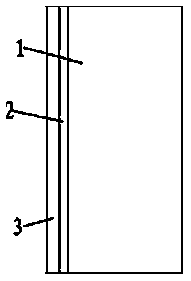
[0030] figure 1 The thermal control coating on the sun-facing surface of the spacec...


PUM


Abstract

The invention discloses a thermal control coating of a spacecraft thermal shield, and aims to provide a thermal control coating of a sunward side of the spacecraft thermal shield, which is good in radiation and heat dissipation effects. The metal film layer is arranged on the sunward side of the heat shield in use and is resistant to high temperature and high in solar radiation reflectivity, and the specially-made aluminum oxide ceramic coating is arranged on the surface of the metal film layer. When the spacecraft is closest to the sun, the average temperature of the thermal control coating on the sunward side of the thermal shield is T, the wavelength corresponding to the maximum value of thermal radiation of a black body with the temperature being T is y, and when the temperature of thespecially-made aluminum oxide ceramic coating is T, the set of the equivalent circle diameters of all crystal grains is X, X-[0.98 * y, 1.02 * y]. The thermal control coating is suitable for thermalprotection of a thermal shield sunward side of a close-range detection solar spacecraft which needs to enter an area which is 50 times the radius of the sun from the surface of the sun.

Description

technical field [0001] The invention relates to the technical field of perihelion probes, in particular to a thermal control coating on the sun-facing surface of a spacecraft heat shield. Background technique [0002] Almost all activities of life on earth depend on the energy from the sun. Any activity and change on the sun affects the safety of human life and the surrounding environment in various ways. With the wide application of modern high-tech systems such as wireless communication, satellite navigation, and the Internet, the impact of high-energy charged particles produced by solar flares, coronal mass ejections, and other solar eruptions on human life has become more and more obvious, similar to the "Carrington Event", "1989 Strong solar activity events such as the "Quebec event" will seriously affect the life and quality of life of modern human beings. In order to deal with the potential impact of strong solar activity on human beings in the future, it is necessar...

Claims


Application Information

Patent Timeline
IPC IPC(8): B64G1/58G06F30/23G06F119/08
CPCB64G1/58
Inventor 黄善杰宋腾飞许方宇程向明张涛张雨辰
Owner YUNNAN ASTRONOMICAL OBSERVATORY CHINESE ACAD OF SCI
Learn More