Dead-beat torque control device, method and system
A torque control and deadbeat technology, applied in the field of deadbeat torque control devices, can solve problems such as system instability and current oscillation
- Summary
- Abstract
- Description
- Claims
- Application Information
AI Technical Summary
Problems solved by technology
Method used
Image
Examples
no. 1 approach
[0052] According to the first embodiment of the present invention, a deadbeat torque control method is provided. figure 1 A schematic flowchart of the deadbeat torque control method is shown. like figure 1 As shown, the method includes the following steps:
[0053] S110, Reference torque Stator voltage μ sα, mu sβ , stator current i sα, i sβ , stator resistance R s , discrete period T s , stator and rotor self-inductance and stator-rotor mutual inductance L s , L r , L m , the number of motor pole pairs p;
[0054] S120, calculating stator flux linkage and rotor flux linkage,
[0055] Among them, the stator flux linkage is calculated according to the following formula: Ψ s = L s i s +L m i r ,
[0056] The rotor flux linkage is calculated according to the following formula: Ψ r = L r i r +L m i s .
[0057] S130, decompose the stator flux linkage in the two-phase stationary coordinate system, and obtain ψ sα and ψ sβ , calculate the torque of the ind...
no. 2 approach
[0085] Due to the calculation delay and one-beat lag of the control cycle in the digital control system, the reference voltage vector calculated at time k acts at time k+1, and reaches the given torque and given flux linkage at time k+2. In order to eliminate the one-beat lag of the digital control system, it is considered to add delay compensation to the dead-beat direct torque controller to predict the two-time electromagnetic torque and stator flux linkage. The calculation process and calculation results in the case of predicting the electromagnetic torque and stator flux linkage twice are described below.
[0086] According to equations (3) and (11), the electromagnetic torque and stator flux linkage at time k+2 can be predicted
[0087]
[0088]
[0089] Due to the reference voltage vector calculated at time k, the given torque and given flux linkage can only be reached at time k+2, that is
[0090]
[0091]
[0092] From equations (3) and (14), the torque an...
no. 3 approach
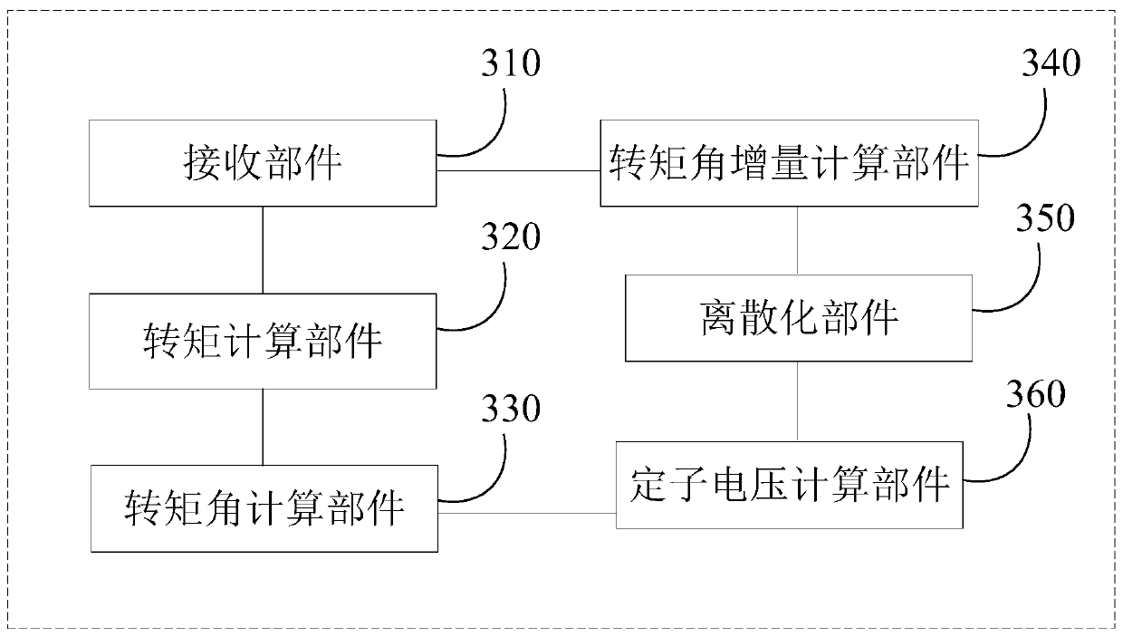
[0101] According to the third embodiment of the present invention, a deadbeat torque control device is also provided. image 3 A schematic block diagram of the device is shown. like image 3 As shown, the device includes:
[0102] The receiving component 310 is used to receive the reference torque Stator voltage μ sα, mu sβ , stator current i sα, i sβ , stator resistance R s , discrete period T s , stator and rotor self-inductance and stator-rotor mutual inductance L s , L r , Lm, the number of motor pole pairs p;
[0103] The torque calculation component 320 is used to calculate the stator flux linkage and the rotor flux linkage according to the following formula: Ψs=Lsi s +L m i r Ψ r = L r i r +L m i s ; Decompose the stator flux linkage in the two-phase stationary coordinate system to get ψ sα and ψ sβ , calculate the torque of the induction motor at time k according to the following formula:
[0104] T e (k)=p[ψ sα (k)i sβ (k)-ψ sβ (k)i sα (k)] ...
PUM
 Abstract
Description
Claims
Application Information
 - Generate Ideas
- Intellectual Property
- Life Sciences
- Materials
- Tech Scout
- Unparalleled Data Quality
- Higher Quality Content
- 60% Fewer Hallucinations
Browse by: Latest US Patents, China's latest patents, Technical Efficacy Thesaurus, Application Domain, Technology Topic, Popular Technical Reports.
© 2025 PatSnap. All rights reserved.Legal|Privacy policy|Modern Slavery Act Transparency Statement|Sitemap|About US| Contact US: help@patsnap.com


