System and method for multiple pipeline ultrasonic non-destructive detection and automatic detection for three-dimensional modelling locating dead pixels

A non-destructive testing and 3D modeling technology, applied in the analysis of solids using sonic/ultrasonic/infrasonic waves, material analysis using sonic/ultrasonic/infrasonic waves, construction, etc. Location and other issues, to achieve the effect of high degree of automation, material saving, saving testing time

Active Publication Date: 2020-01-07
JIANGSU UNIV +1
View PDF3 Cites 5 Cited by
  • Summary
  • Abstract
  • Description
  • Claims
  • Application Information

AI Technical Summary

Problems solved by technology

[0004] The technical problem to be solved by the present invention is to provide a multi-pipe ultrasonic non-destructive testing system and a three-dimensional construction system for the defects in the prior art that cannot determine the specific three-dimensional position of the defect in the pile foundation, the degree of automation is low, and the accuracy of determining the bad point is not enough. Automatic Detection System for Die Locating Dead Points

Method used


Image

  • System and method for multiple pipeline ultrasonic non-destructive detection and automatic detection for three-dimensional modelling locating dead pixels
  • System and method for multiple pipeline ultrasonic non-destructive detection and automatic detection for three-dimensional modelling locating dead pixels
  • System and method for multiple pipeline ultrasonic non-destructive detection and automatic detection for three-dimensional modelling locating dead pixels

Examples


Embodiment Construction

[0049] In order to have a further understanding and understanding of the structural features of the present invention and the achieved effects, the preferred embodiments and accompanying drawings are used for a detailed description, as follows:

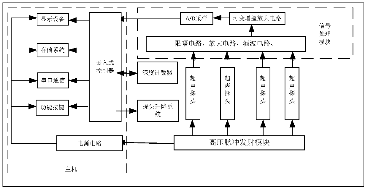
[0050] The present invention implements a multi-pipeline ultrasonic nondestructive testing system, such as figure 1 The entire system shown includes a high-voltage pulse transmission module, a signal processing module, a probe lifting system, an ultrasonic probe, a depth counter, and a host. The whole system is controlled by the host computer. The signal processing module, the probe lifting system, and the depth counter are all interconnected with the host; at the same time, the host and the high-voltage pulse transmission module send control information in one direction; multiple ultrasonic probes are composed of ultrasonic transducers, and the ultrasonic transducers Connect with the high-voltage pulse transmission module and the si...


PUM


Abstract

The invention discloses a system and method for multiple pipeline ultrasonic non-destructive detection and automatic detection for three-dimensional modelling locating dead pixels. The system for multiple pipeline ultrasonic non-destructive detection and automatic detection for the three-dimensional modelling locating dead pixels comprises a high-pressure pulse emission module, a signal processingmodule, a probe lifting system, ultrasonic wave probes, depth counters and a host computer. Each ultrasonic wave probe comprises an ultrasonic wave emission transducer and a receiving transducer correspondingly. Cables are connected to the rear of the ultrasonic wave probes and fixed to cable grooves. Photoelectric counters are installed on the cable grooves, and the cables pass through the photoelectric counters. Each depth counter is constituted by combination of a cable coated with black and white paint at an interval of 0.5cm and a corresponding photoelectric counter, and each depth counter is connected with the host computer. In the probe lifting system, the ultrasonic wave probes are controlled to rise and fall through a stepping motor by the host computer according to information of the depth counters. According to the system for multiple pipeline ultrasonic non-destructive detection and automatic detection for the three-dimensional modelling locating dead pixels, real-time comparison is conducted through relative standard data and detection data acquired from calculation and pre-measuring of pile foundation, and the detection time is saved.

Description

technical field [0001] The invention relates to ultrasonic non-destructive testing of foundation piles, in particular to an ultrasonic non-destructive testing system and a detection method for porous ultrasonic three-dimensional positioning of bad points. Background technique [0002] The ultrasonic foundation pile non-destructive testing system mainly judges the integrity of the foundation pile through the acoustic parameters such as the propagation speed, amplitude and frequency of the sound wave in different media. At present, the existing detection method: through the acoustic tube of the pile foundation, the ultrasonic transmitting and receiving transducer is used to transmit and receive the acoustic wave data, and the position of the defect can only be determined on a section, and it is impossible to specifically determine the position of the defect in the foundation pile. specific three-dimensional position. [0003] At present, the existing ultrasonic non-destructiv...

Claims


Application Information

Patent Timeline
IPC IPC(8): E02D33/00G01N29/11G01N29/265
CPCE02D33/00G01N29/11G01N29/265G01N2291/0289G01N2291/2698
Inventor 李天博戴松仁陈宇川肖海龙
Owner JIANGSU UNIV
Why Eureka
Try Eureka