
Head-mounted eye movement tracking device

An eye-tracking and head-mounted technology, applied in mechanical mode conversion, eye testing equipment, diagnosis, etc., can solve problems such as large amount of calculation, poor real-time performance, and poor user experience, and achieve low hardware resource occupancy , Low hardware performance requirements, less use restrictions

Pending Publication Date: 2019-12-31
CHANGZHOU INST OF TECH
View PDF0 Cites 3 Cited by
  • Summary
  • Abstract
  • Description
  • Claims
  • Application Information

AI Technical Summary

Problems solved by technology

Although eye-tracking devices have broad application prospects, most of the existing domestic eye-tracking devices are head-restricted. The subject needs to fix the head on a flat surface and the head cannot move during the measurement , very inflexible
Moreover, the distance between the camera and the human eye is relatively long, and the pixels of the human eye account for a relatively small proportion of each frame of image captured by the camera, which cannot avoid the interference caused by complex background images, resulting in high complexity and a large amount of calculation for tracking algorithms on non-wearable devices. , has high requirements for hardware computing speed, which occupies a lot of hardware resources of the controlled device, poor real-time performance, and poor user experience

Method used


Image

  • Head-mounted eye movement tracking device
  • Head-mounted eye movement tracking device
  • Head-mounted eye movement tracking device

Examples


specific Embodiment approach 1

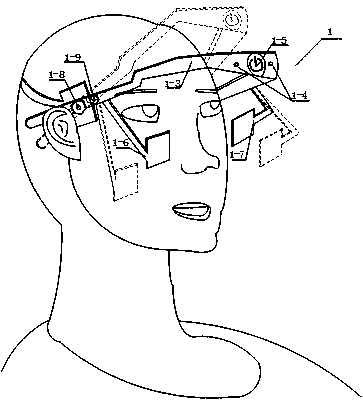
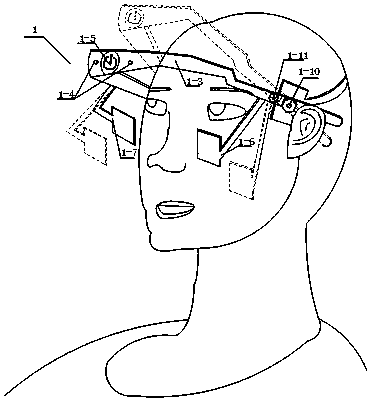
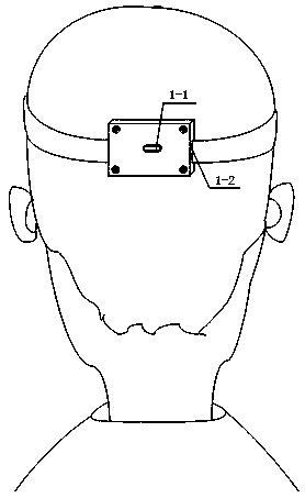
[0020] The head-mounted eye-tracking device of this embodiment combines figure 1 , figure 2 , image 3 As shown, a head-mounted eye tracking device includes:

[0021] The head wearer 1 is used to wear the device on the heads of different individuals and fix and protect the electronic components required for the device; the wearer 1 has a USB Type-C input socket 1-1, and a rear fixing cassette 1-2 , Front fixed cassette 1-3, LED indicator light 1-4, multi-function touch button 1-5, left camera bracket 1-6, right camera bracket 1-7, cassette elastic adjustment left knob 1-8, left Camera bracket rotation adjustment knob 1-9, cassette tightness adjustment right knob 1-10, right camera bracket rotation adjustment knob 1-11;

[0022] Among them, the multi-function light touch button 1-5 is located in the middle position of the front side of the front fixed cassette 1-3, and is used to open or close the eye movement tracking device, indicate the switch state, and switch the worki...

specific Embodiment approach 2

[0028] Specific Embodiment 2: Different from Specific Embodiment 1, the head-mounted eye-tracking device of this embodiment combines figure 1 , Figure 4 shown, including:

[0029] A miniature infrared camera module 2, an eye video image processing module 3, a wireless data transmission module 4 and a power supply module 5 built into the head wearable 1; the eye video image processing module 3 is respectively connected to the miniature infrared camera module 2, wireless data transmission module Module 4, power supply module 5; among them, there are 2 micro-infrared camera module cameras, integrated with micro-infrared light-emitting diodes, responsible for the collection of human eye video image data; eye video image processing module 3 is responsible for the processing of the entire eye tracking device algorithm, wireless The data transmission module 4 is used to wirelessly transmit the results obtained after the eye video image processing module 3 processes the eye video im...

specific Embodiment approach 3

[0030] Specific Embodiment 3: Different from Specific Embodiment 2, the head-mounted eye-tracking device of this embodiment combines Figure 4 Shown:

[0031] Eye video image processing module (3) comprises eye video image data cache circuit unit 3-1, FPGA image processing and control circuit unit 3-2, LED indicator light driving circuit unit 3-3 and button circuit unit 3-4; The FPGA image processing and control circuit unit 3-2 in the eye video image processing module 3 is respectively connected to the eye video image data buffer circuit unit 3-1, the LED indicator light driving circuit unit 3-3 and the button circuit unit 3-4 The eye video image data cache circuit unit 3-1 is used to realize that the video image data output by the miniature infrared camera module 2 is cached in units of frames; the FPGA image processing and control circuit unit 3-2 is used for the eye video image The data cache circuit unit 3-1 reads the eye video image data in units of frames and processes...


PUM


Abstract

The invention discloses a head-mounted eye movement tracking device. The head-mounted eye movement tracking device is worn on the head of a user and comprises a head wearing piece, a micro infrared camera module arranged in the head wearing piece, an eye video image processing module, a wireless data transmission module and a power module. When the head-mounted eye movement tracking device is wornon the head, an infrared camera bracket on the head wearing piece is adjusted to be aligned with the eyes, thus presenting a clear eye image; eyeball movement tracks can be recorded, and reference isprovided for mental disease diagnosis; and human eye sight information can be tracked, and blinking actions can be detected and converted into mouse signals to control and use digital terminals suchas computers and mobile phones. According to the head-mounted eye movement tracking device, assistance can be provided for doctors to perform pathological examination and mental disease diagnosis on the eyes of patients, and the cursor can be controlled to roughly replace the mouse through the eye movement information, so that convenience is brought to people who are inconvenient to use the mouseby hands, and the equipment is low in cost and convenient to wear.

Description

technical field [0001] The present invention relates to the field of eye-tracking devices, in particular to a head-mounted eye-tracking device. Background technique [0002] The eye is an important organ for human beings to obtain information from the surrounding world. By accurately measuring a person's gaze point, it can provide an important basis for studying human psychological activities and extracting psychological awareness. The gaze point can be used instead of the mouse or touch operation to realize the use of gaze point Perform human-computer interaction; eye tracking devices, as a line-of-sight measurement device, have broad application prospects in all walks of life, including rehabilitation medicine, advertising design, game design and human-machine interface design and many other fields. Although eye-tracking devices have broad application prospects, most of the existing domestic eye-tracking devices are head-restricted. The subject needs to fix the head on a f...

Claims


Application Information

Patent Timeline
Patent Type & Authority Applications(China)
IPC IPC(8): G06F3/01G02B27/00A61B3/113A61B3/14
CPCG06F3/013G02B27/0093A61B3/113A61B3/14
Inventor 王鹏温宏韬尚子渠孙鑫悦陈化良沈翔
Owner CHANGZHOU INST OF TECH
Learn More