
Natural cooling refrigeration system

A technology of natural cooling and refrigeration system, applied in the directions of refrigerators, refrigeration components, refrigeration and liquefaction, etc., can solve the problems of incapable of compressor cooling, reduction of refrigerant flow, insufficient energy saving, high efficiency and stability of refrigeration system, and achieve the overall design Reasonable, reduce the cooling demand, and improve the effect of natural cooling

Pending Publication Date: 2019-12-31
WUXI VOCATIONAL & TECHN COLLEGE
View PDF1 Cites 1 Cited by
  • Summary
  • Abstract
  • Description
  • Claims
  • Application Information

AI Technical Summary

Problems solved by technology

[0004] Although this kind of refrigeration system can solve the problem that the flow rate of liquid refrigerant in the existing refrigeration system is reduced under the condition of low pressure ratio and cannot cool the compressor, but: the refrigeration system is still not energy-saving, efficient and stable enough to independently control refrigeration The independent work of some components in the system cannot guarantee a relatively stable chilled water supply temperature throughout the year

Method used


Image

  • Natural cooling refrigeration system
  • Natural cooling refrigeration system
  • Natural cooling refrigeration system

Examples


Embodiment 1

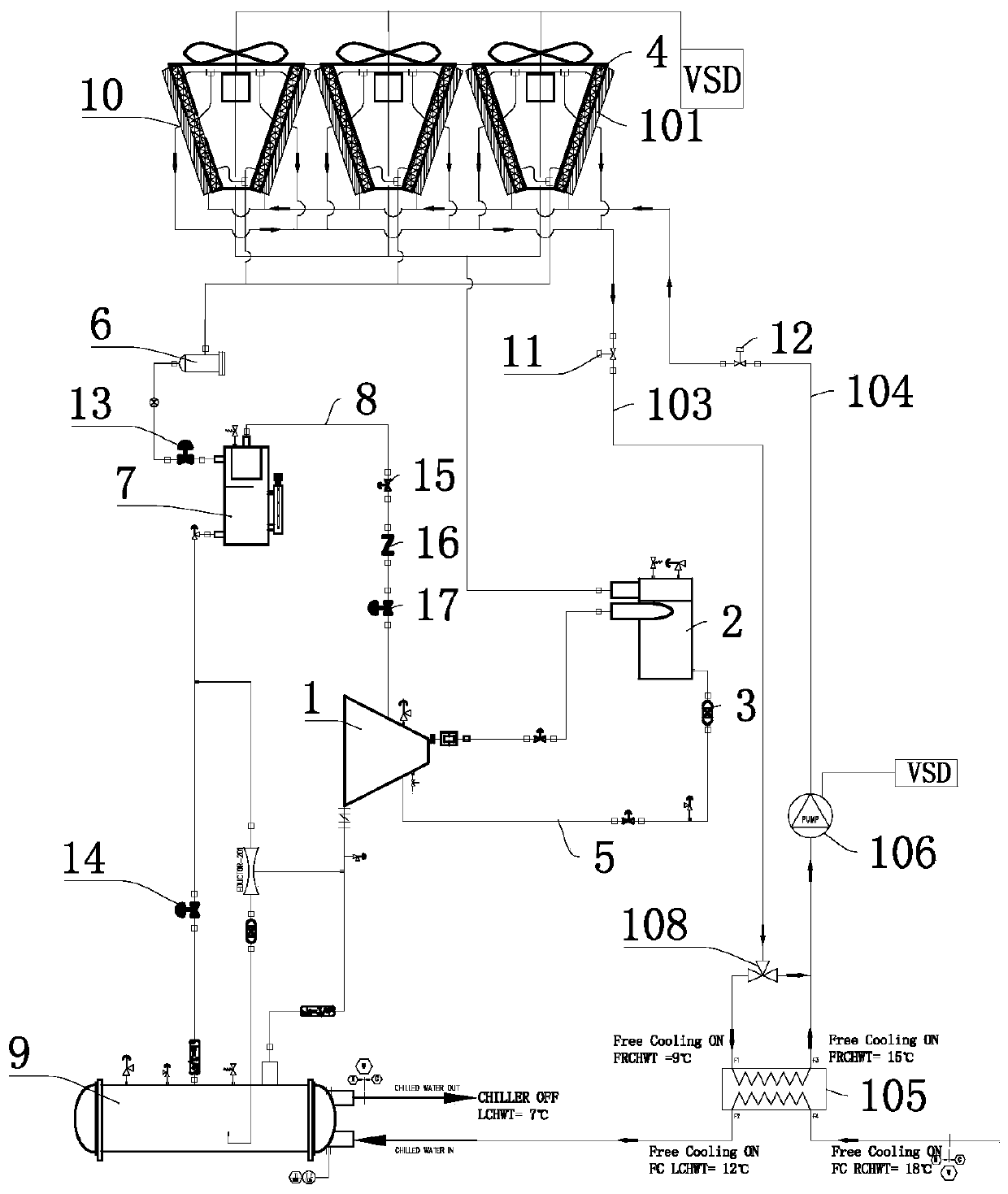
[0029] Embodiment 1: a kind of natural cooling refrigeration system, as figure 1 As shown, the compressor 1 is connected with an oil separator 2, an evaporator 9 and a flash economizer 7 respectively, one end of the oil separator 2 is connected with the air-cooled condenser 4, and the other end is connected with the first filter 3, Compressor 1, oil separator 2, and first filter 3 form a first loop 5, one end of the second filter 6 is connected to the air-cooled condenser 4, and the other end is connected to the flash economizer 7, the flash economizer The compressor 7 communicates with the compressor 1, the compressor 1, the oil separator 2, the air-cooled condenser 4, the second filter 6 and the flash economizer 7 form a second loop 8, and the first-stage electronic expansion valve 13 Installed between the second filter 6 and the flash economizer 7 .

[0030] The flash economizer 7 and the evaporator 9 communicate with each other, and the second-stage electronic expansion v...

Embodiment 2

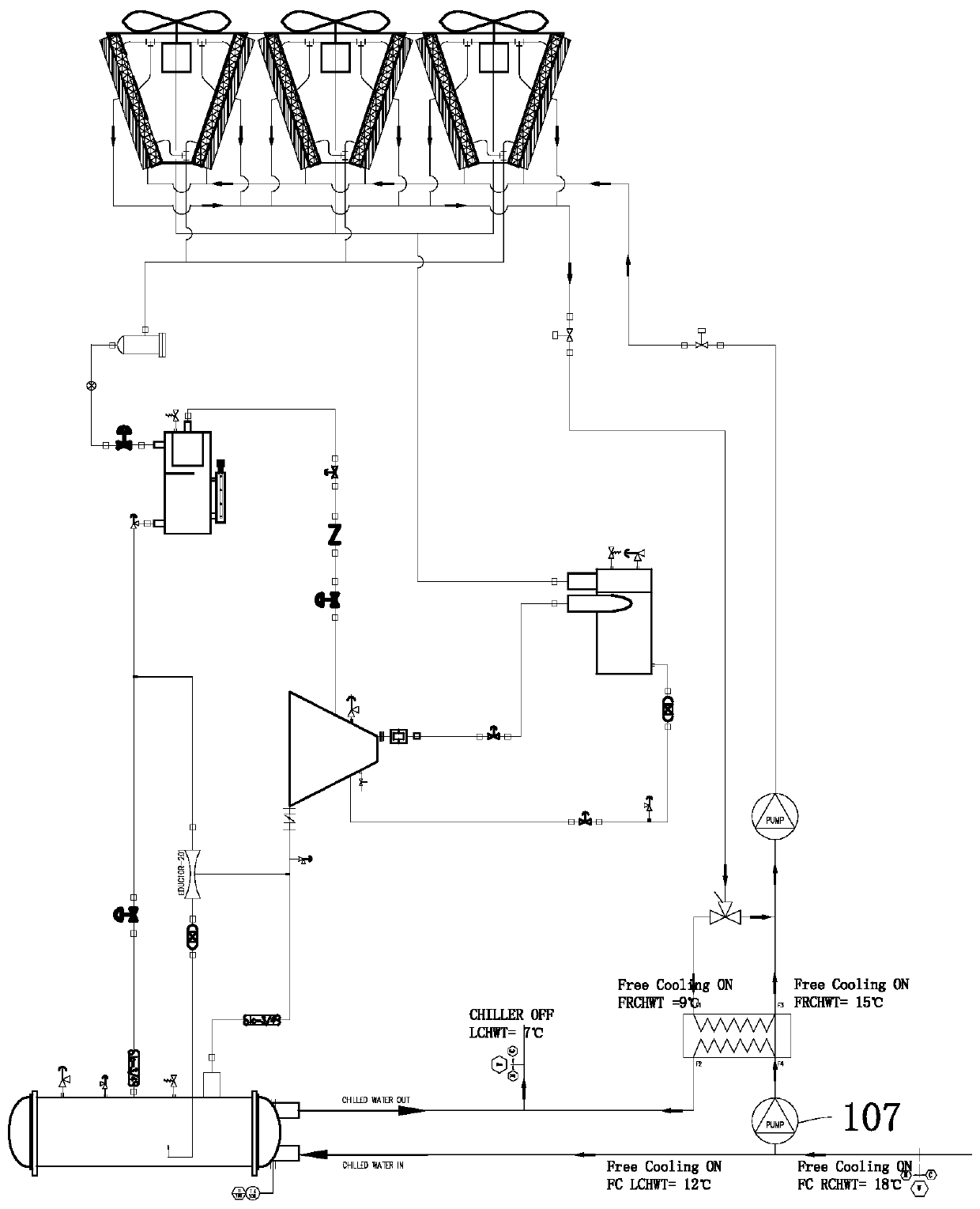
[0037] Embodiment 2: as figure 1 and figure 2 As shown, the water system of the evaporator 9 and the water system of the natural cooling coil 101 are connected in series, and a second water pump 107 is installed on the return water pipe of the evaporator 9 to overcome the water flow of the evaporator 9 through the plate heat exchanger. pressure drop loss.

Embodiment 3

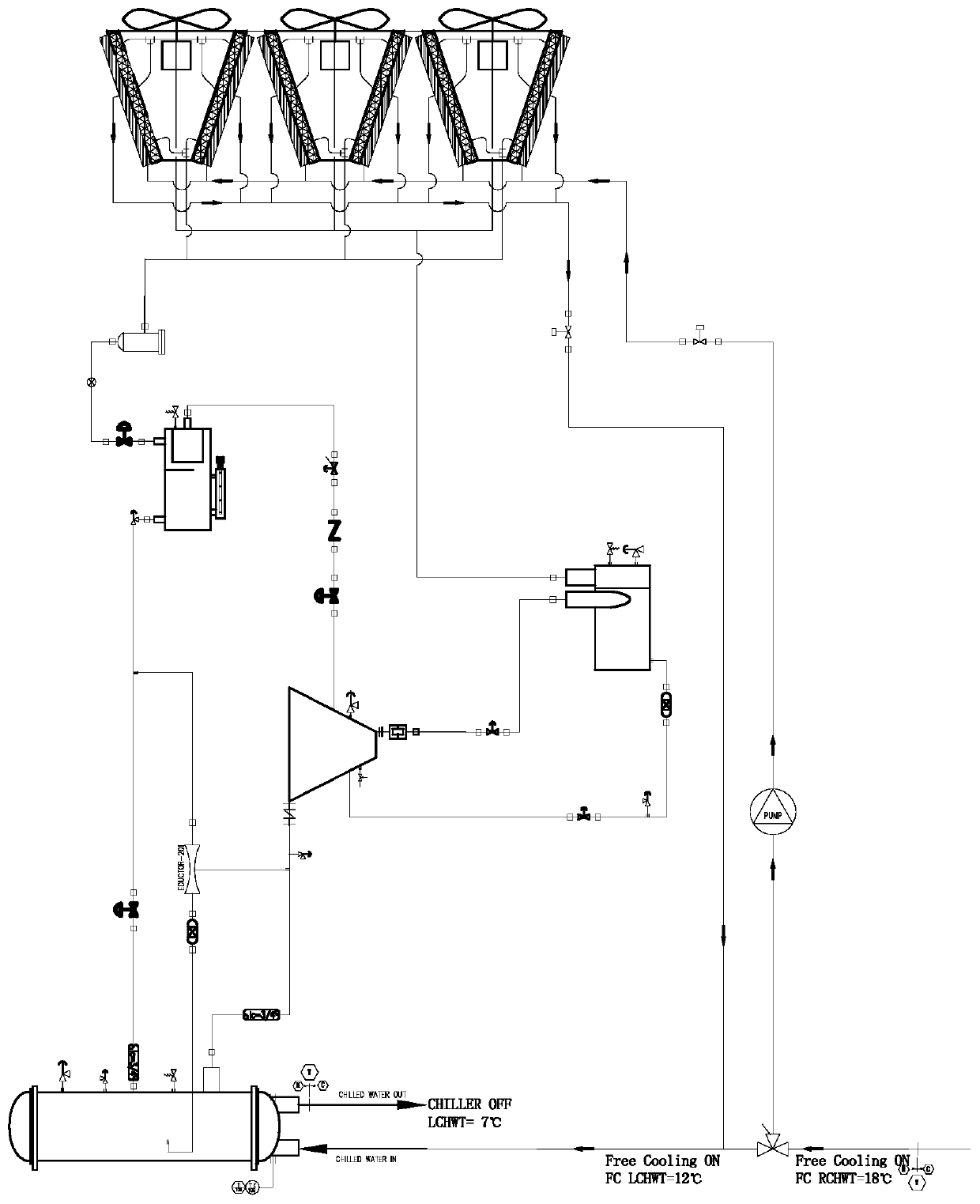
[0038] Embodiment 3: as figure 1 and image 3 As shown, the water system of the evaporator 9 and the water system of the natural cooling coil 101 are connected in series, but the direct connection method is adopted, and the plate heat exchanger is canceled, that is, the two water systems are mixed together, and the linear three-way The valve 108 is connected to the evaporator 9, the first waterway shut-off valve 11 and the second waterway shut-off valve 12, the first water pump 106 is installed between the second waterway shut-off valve 12 and the linear three-way valve 108, and the linear three-way valve 108 is installed on On the water outlet pipeline 104.

[0039] In the water system, the linear three-way valve 108 is used to adjust the water flow into the natural cooling coil 101 to control the heat transfer (cooling capacity) of the natural cooling coil 101. The water system is equipped with a first water pump 106 to overcome the flow through the natural cooling. Pressu...


PUM


Abstract

The invention discloses a natural cooling refrigeration system, and aims at providing the energy-saving, efficient and stable natural cooling refrigeration system. The main point of the technical scheme in that the natural cooling refrigeration system comprises a compressor, wherein an oil separator is arranged on the compressor in a communication mode, a first filter and an air cooling condenserare respectively arranged on the oil separator in a communication mode, the compressor communicates with the first filter, the compressor, the oil separator and the first filter form a first circuit,a second filter is arranged on the air cooling condenser in a communication mode, a flash evaporation type economizer is arranged at the bottom of the second filter in a communication mode, the flashevaporation type economizer communicates with the compressor, the compressor, the oil separator, the air cooling condenser, the second filter and the flash evaporation type economizer form a second circuit, an evaporator is arranged on the flash evaporation type economizer in a communication mode, a natural cooling system is arranged on the evaporator, a water route of the natural cooling system and a water route of the evaporator communicate with each other in a series connection or parallel connection mode, and the natural cooling system is of an integrated structure or external separating type structure.

Description

technical field [0001] The invention relates to the technical field of refrigeration systems, in particular to a natural cooling refrigeration system. Background technique [0002] The refrigeration system is composed of refrigerant and four major parts, namely compressor, condenser, expansion valve and evaporator. The volume of the steam is reduced and the pressure is increased. The compressor sucks the lower-pressure working medium steam from the evaporator, raises the pressure, and sends it to the condenser, where it is condensed into a liquid with a higher pressure. After being throttled by the throttle valve, it becomes a liquid with a lower pressure, and then it is sent to the evaporator, where it absorbs heat and evaporates to become a steam with a lower pressure, and then it is sent to the inlet of the compressor to complete the refrigeration cycle. [0003] At present, the Chinese patent with the publication number CN 108131853 A discloses a refrigeration system, w...

Claims


Application Information

Patent Timeline
IPC IPC(8): F25B1/00F25B41/04F25B41/06F25B49/02F25B41/20F25B41/34
CPCF25B1/00F25B49/02F25B41/20F25B41/31
Inventor 商萍君王丽梅赵欣欣张丽仙屈海香
Owner WUXI VOCATIONAL & TECHN COLLEGE
Learn More