Compressed air exhausting polishing device and compressed air exhausting polishing method for polishing blind hole

A polishing device and blind hole technology, applied in surface polishing machine tools, machine tools suitable for grinding workpiece edges, grinding/polishing equipment, etc. Friendly and safe effect

Pending Publication Date: 2019-12-24
ZHEJIANG UNIV OF TECH
View PDF0 Cites 0 Cited by
  • Summary
  • Abstract
  • Description
  • Claims
  • Application Information

AI Technical Summary

Problems solved by technology

[0004] The purpose of the present invention is to solve the problem that the existing polishing method cannot polish the blind hole printed by 3D printing technology, and proposes a pumping air polishing device and method for blind hole polishing. The negative pressure makes the abrasive grain flow impact the blind hole of the workpiece, and the blind hole type workpiece can be polished. The blind hole of the workpiece to be processed is in a negative pressure state by pumping air, so that the abrasive grain flow can enter the blind hole more smoothly. During the process, the abrasive grain flow is used to repeatedly impact the blind hole of the workpiece, and the blind hole is micro-cut and polished

Method used


Image

  • Compressed air exhausting polishing device and compressed air exhausting polishing method for polishing blind hole
  • Compressed air exhausting polishing device and compressed air exhausting polishing method for polishing blind hole
  • Compressed air exhausting polishing device and compressed air exhausting polishing method for polishing blind hole

Examples


Embodiment Construction

[0045] The present invention will be further described below in conjunction with accompanying drawing:

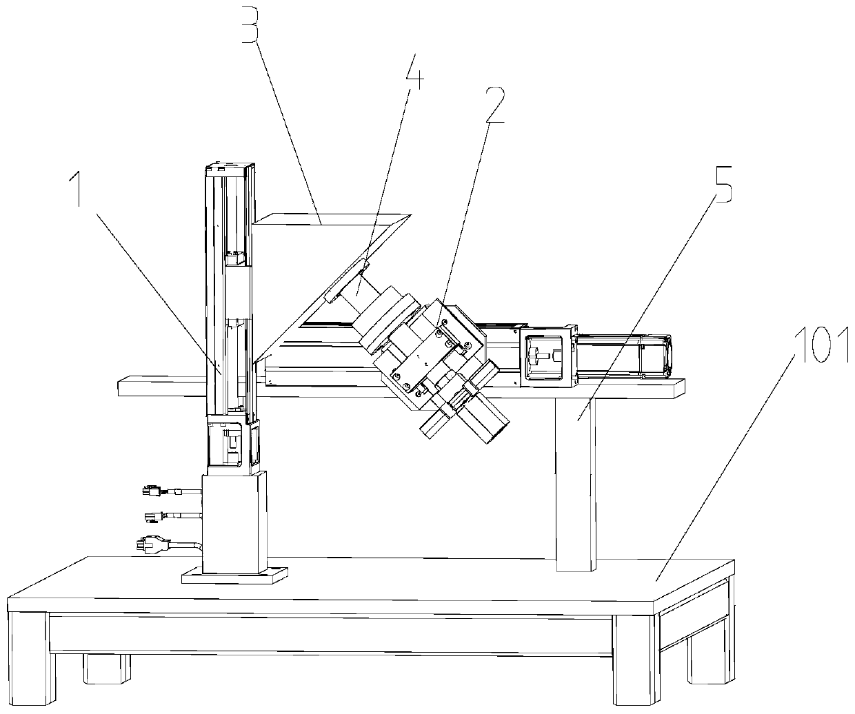
[0046] Such as Figure 1-8 As shown, a pumping gas polishing device for blind hole polishing, a pumping gas polishing device for blind hole polishing, includes a worktable 101 , a moving positioning component 1 , a flow channel component 2 and a support clamping component 3 .

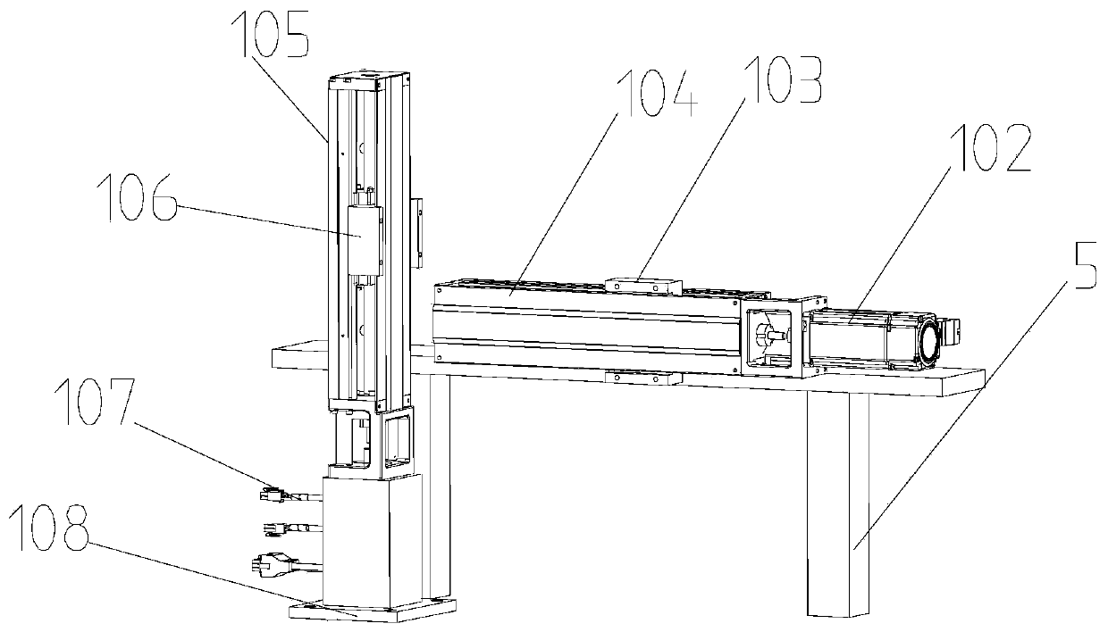
[0047] The mobile positioning assembly 1 includes a horizontal module mounting frame 5, a horizontal linear module 104, a horizontal module driving motor 102, a vertical linear module 105 and a vertical module driving motor 107, and the horizontal module mounting frame 5 Fixed on the workbench 101; the horizontal linear module 104 is horizontally fixed on the horizontal module mounting frame 5, the horizontal module drive motor 102 is fixed on one end of the horizontal linear module 104, and the horizontal module drive motor 102 The drive shaft is connected to the horizontal linear module 104 and dr...


PUM


Abstract

The invention discloses a compressed air exhausting polishing device and a compressed air exhausting polishing method for polishing a blind hole. The compressed air exhausting polishing device comprises a movable positioning assembly, a runner assembly and a supporting and clamping assembly, wherein the movable positioning assembly comprises a worktable, a horizontal module mounting rack, a horizontal linear module, horizontal module driving motors, a vertical linear module and a vertical module driving motor; the supporting and clamping module comprises a supporting block, a secondary clamping head and a vertical mounting base; the runner assembly comprises a main clamping head, a hollow runner fixing seat, a runner fixing plate, a sliding rail connecting plate, an exhausting port one-wayvalve, a gas-liquid abrasive particle flow connector, an abrasive particle flow inlet valve, a compressed air port one-way valve, a runner connector, a hollow runner, a ring flange and a main clamping head O-shaped ring. The compressed air exhausting polishing device can polish blind holes of blind hole workpieces; and blind holes of to-be-polished workpieces are positioned in a negative pressurestate by exhausting air, so that abrasive particle flows can enter the blind holes more smoothly.

Description

technical field [0001] The present invention relates to the field of abrasive particle flow polishing, and more specifically relates to a suction gas polishing device and method for blind hole polishing, which uses periodic positive and negative pressures to make abrasive flow impact workpieces. Background technique [0002] 3D printing technology is also called additive manufacturing technology, which is an advanced manufacturing technology called rapid prototyping in China. Its essential principle is discrete and accumulation. The manufacture of three-dimensional solids is transformed into the accumulation of two-dimensional layers and continuous superposition along the forming direction, and finally realizes the manufacture of three-dimensional solids. As the use of 3D printing technology becomes more and more widespread, more and more blind hole products are produced by 3D printing technology. Compared with the through hole, the blind hole refers to the hole that does n...

Claims


Application Information

Patent Timeline
IPC IPC(8): B24B31/116B24B31/12B24B41/06
CPCB24B31/116B24B31/12B24B41/06Y02P70/10
Inventor 张利纪仁全曾晰李研彪计时鸣
Owner ZHEJIANG UNIV OF TECH
Why Eureka
Try Eureka