
A kind of vacuum degreasing sintering furnace and using method thereof

A vacuum degreasing and sintering furnace technology, applied in furnaces, furnace types, lighting and heating equipment, etc., can solve problems such as prolonging degreasing time, speeding up degreasing speed, and binder pollution, improving performance and quality, and reducing the degree of pollution. , the effect of prolonging the service life

Active Publication Date: 2021-06-18
NINGBO HIPER VACUUM TECH CO LTD
View PDF6 Cites 0 Cited by
  • Summary
  • Abstract
  • Description
  • Claims
  • Application Information

AI Technical Summary

Problems solved by technology

[0003] 1. Dust influence: Graphite and carbon fiber are easy to generate dust. Graphite dust and carbon fiber dust will be brought into the material box with the airflow and adhere to the product in the material box. During sintering, the surface of the product is prone to defects, and the carbon content in the product is also high. As it increases, the performance of products made of stainless steel such as 316, 304, 316L, 17-4PH and other materials with high requirements will decrease.
[0004] 2. Moisture impact: When the furnace door is opened, the moisture in the air will enter the furnace and into the carbon fiber heat insulation cylinder. Under the vacuum high temperature, the moisture will turn into steam and run out, and the moisture will oxidize the surface of the product, slightly Yellowing in some cases, graying and bluish in severe cases
[0005] 3. Leakage effect: Leakage of vacuum furnace is unavoidable, just control the leakage at a low level, air enters from the furnace door and other positions, and it is easy to contact with the sintered product and affect the performance of the product
However, direct contact between the ceramic plate and the graphite material plate will cause a carbothermal reduction reaction to generate Al and Al 2 o 3 When new substances are attached to the surface of the product, when the furnace is evacuated or cooled, the upper cover of the material box is opened, and the new substances generated will go to the outside of the material box, enter the carbon fiber insulation tube, or adhere to the inner wall of the furnace The upper polluted heat insulation cylinder will run into the material box during the operation of the next furnace process. After such a cycle, when a certain amount is reached, it will be deposited on the surface of the product, resulting in poor product surface and affecting product performance.
[0007] 5. The influence of binder pollution: the vacuum environment is conducive to the gasification of the binder, but it is also easy to diffuse the binder. When degreasing, the binder will come out of the product and become vapor and diffuse, and some will leak into the Go outside the material box, enter the carbon fiber heat insulation tube, or attach to the inner wall of the furnace, polluting the furnace
[0013] 3. When the metal powder is made, a layer of oxide layer will be formed on the surface. If the oxide layer is not removed, it will hinder the diffusion during sintering, so that the product cannot be dense. Using hydrogen can reduce carbon dioxide
In the prior art, the scrap rate is extremely high, and the solution is to prolong the degreasing time, so that the binder in the product can be discharged as much as possible
At low temperatures, the oxygen in the air reacts with the binder, which can speed up the degreasing speed. Combustion) However, in the current vacuum degreasing and sintering furnace technology, the use of oxygen is restricted, because oxygen will react with graphite above 300 ° C, thereby depleting graphite parts
In addition, as with the restricted use of hydrogen, even if the temperature of the material box is controlled at about 200 ° C, oxygen is charged into the furnace, and before entering the material box, it will pass through different temperature regions, and it will react to the graphite parts and heat insulation cylinders in the reaction area. , especially the heating material, the temperature is higher than the temperature of the material box, and the loss is large

Method used


Image

  • A kind of vacuum degreasing sintering furnace and using method thereof
  • A kind of vacuum degreasing sintering furnace and using method thereof
  • A kind of vacuum degreasing sintering furnace and using method thereof

Examples


Embodiment 1

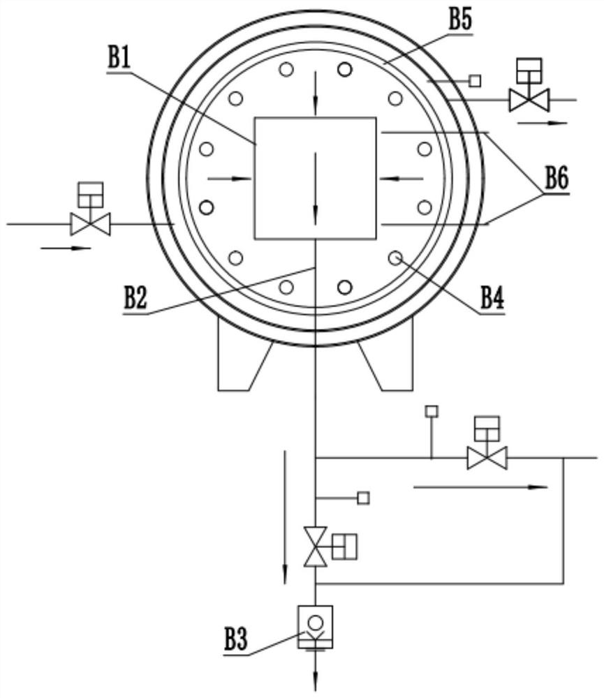
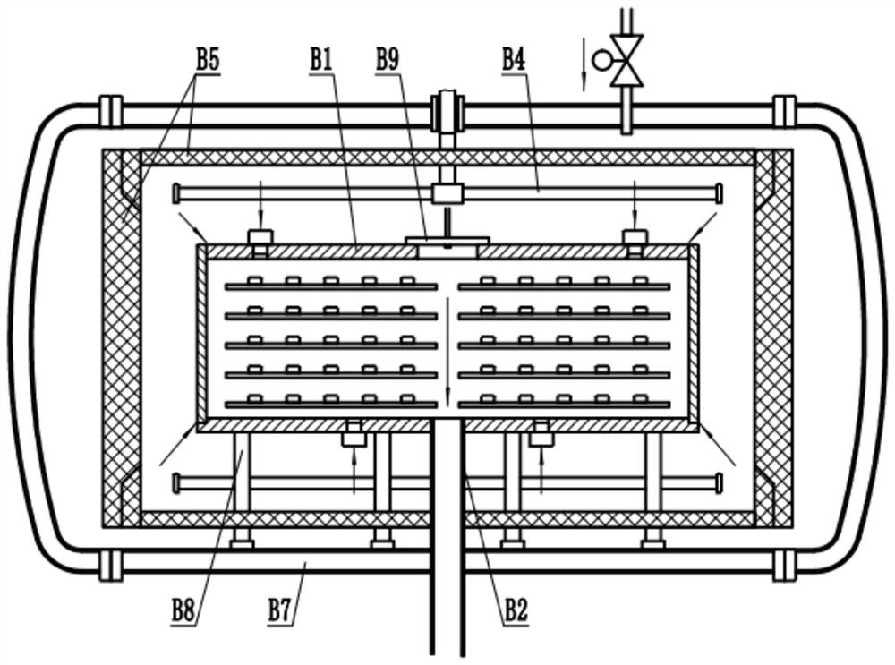
[0051] Such as Figure 4-Figure 5 As shown: this embodiment provides a vacuum degreasing sintering furnace, including a furnace body 1 and a carbon fiber heat insulation cylinder 2 arranged inside the furnace body 1, and a graphite material box 3 is arranged inside the carbon fiber heat insulation cylinder 2, and the graphite material box 3 A material box loam cake 24 is provided in the middle of the upper side. There are several graphite heating rods 21 evenly distributed along the circumferential direction between the carbon fiber heat insulating cylinder 2 and the graphite material box 3, and several thermocouples 22 are respectively arranged on the upper side and the lower side of the graphite material box 3, and the thermocouples 22 are respectively used to detect graphite materials. The temperature of the upper and lower sides of box 3.

[0052] The graphite material box 3 is provided with an inner gas filling port 4 and an inner gas extraction port 5, and the inner gas...

Embodiment 2

[0058] Such as Image 6 Shown: The difference between this embodiment and Embodiment 1 is that: the inner gas filling port 4 is arranged in the middle of the upper side of the graphite material box 3, the inner air extraction port 5 is arranged at the two ends of the lower side of the graphite material box 3, and the two rows of material plates 13 Adjacent ends are respectively provided with a gas guiding device 12 , the upper cover 24 of the material box is arranged on the two ends of the upper side of the graphite material box 3 , and the outer air extraction port 9 is arranged on the lower side of the furnace body 1 . For other technical features and usage methods, please refer to Embodiment 1.

Embodiment 3

[0060] Such as Figure 7 Shown: The difference between this embodiment and Embodiment 1 is that: the inner gas filling port 4 is arranged on one end of the upper side of the graphite material box 3, such as the right end, and the inner air extraction port 5 is arranged on the other end of the lower side of the graphite material box 3, such as the left end , The material plate 13 is provided in multiple layers, only the right end of the material plate 13 is provided with the air guiding device 12, and the outer air extraction port 9 is arranged on the lower side of the furnace body 1. For other technical features and usage methods, please refer to Embodiment 1.


PUM


Abstract

The invention discloses a vacuum degreasing sintering furnace and a method for using the same, and relates to the technical field of special equipment for powder metallurgy, powder ceramic sintering and the like. A graphite material box (3) is provided with an inner air filling port (4) and an inner air extraction port (5) ), the inner gas filling port (4) is connected with the inner gas filling pipe (6), the inner gas extraction port (5) is connected with the inner gas extraction tube (7), and the body of furnace (1) is provided with the outer gas charging port (8) and the outer gas extraction port (9), the outer inflation port (8) is communicated with an outer inflation pipe (10), and the outer air extraction port (9) is communicated with an outer air extraction pipe (11). The vacuum degreasing and sintering furnace is mainly based on filling the graphite material box (3) with process gas, supplemented by filling the graphite material box (3) with an inert gas, and isolating the atmosphere inside and outside the graphite material box (3) to reduce the graphite material. Various impure atmospheres and pollutants outside the box (3) enter the graphite material box (3) and affect the sintering of the product, improve product quality and production speed, reduce the pollution degree in the furnace, and prolong the use of the vacuum degreasing sintering furnace life, and makes it possible to use hydrogen for high-temperature sintering and oxygen for low-temperature degreasing.

Description

technical field [0001] The invention relates to the technical field of special equipment for manufacturing powder metallurgy and powder ceramic sintering, and in particular to a vacuum degreasing sintering furnace and a use method thereof. Background technique [0002] Graphite hot field vacuum degreasing sintering furnace is used for degreasing and sintering the metal powder body. The main components in the furnace are made of carbon fiber and graphite. Graphite has excellent electrical conductivity, super heat resistance, high reliability and Lightweight, easy to process, long life and other advantages, it is one of the main materials for vacuum sintering furnaces, but there are also the following problems: [0003] 1. Dust influence: Graphite and carbon fiber are easy to generate dust. Graphite dust and carbon fiber dust will be brought into the material box with the airflow and adhere to the product in the material box. During sintering, the surface of the product is pro...

Claims


Application Information

Patent Timeline
Patent Type & Authority Patents(China)
IPC IPC(8): F27B17/00B22F3/00B22F3/10
CPCF27B17/00B22F3/003B22F3/1021B22F3/1007Y02P10/143
Inventor 刘鹏徐文立胡芳
Owner NINGBO HIPER VACUUM TECH CO LTD
Learn More