
Crawler brake oil pressure flow meter oiling equipment for construction machinery

A technology of construction machinery and brake oil pressure, which is applied in special distribution devices, packaging, distribution devices, etc., can solve the problems of high proportion of petroleum equipment usage, oil waste, spilling, etc., and achieve convenient and fast refueling process, structure Rigorous design to enhance the effect of volatilization

Inactive Publication Date: 2019-12-20
徐州贝峰机械制造有限公司
View PDF7 Cites 0 Cited by
  • Summary
  • Abstract
  • Description
  • Claims
  • Application Information

AI Technical Summary

Problems solved by technology

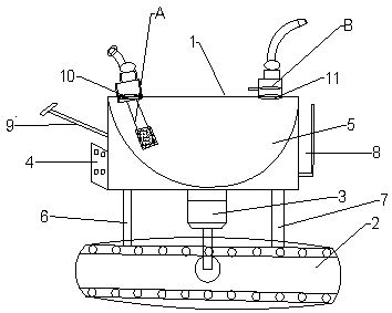
[0002] In the current stage of engineering construction, the use of petroleum equipment accounts for a high proportion. The reason is that the use of petroleum as a power fuel has enough power, and there are no geographical restrictions and no need for other equipment connections to assist in increasing kinetic energy, so refueling during the project The vehicles have been well utilized. Some of the refueling vehicles in the current technology are manual push-pull vehicles or barreled refueling methods. In areas with complex environments and areas that are not conducive to walking, the current refueling equipment is not easy to use, making The refueling speed is slow, and the transported fuel tank is often used to directly infuse refueling, which requires the assistance of multiple people to operate, and the oil will be spilled during the refueling process, resulting in oil surface stains and waste of oil in the engineering environment, increasing the project cost

Method used


Image

  • Crawler brake oil pressure flow meter oiling equipment for construction machinery
  • Crawler brake oil pressure flow meter oiling equipment for construction machinery
  • Crawler brake oil pressure flow meter oiling equipment for construction machinery

Examples


Embodiment Construction

[0012] The present invention will be further described below in conjunction with the drawings.

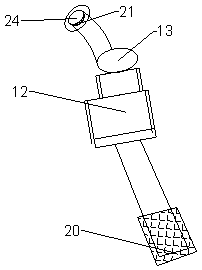
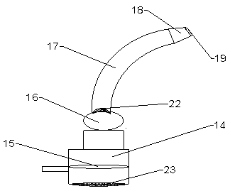
[0013] Such as Figure 1 to Figure 3 As shown, the present invention is a crawler brake oil pressure flow meter refueling equipment for construction machinery, including an equipment body shell 1, a crawler device 2, an electric motor 3, and a control board device 4. The device body shell 1 is provided with a circle The arc container 5, the interlayer between the bottom of the arc container 5 and the inside of the equipment body shell 1 is set as a vacuum hollow, the bottom of the equipment body shell 1 is fixedly connected to one side of the crawler device 2 by a pillar rod I6, and the bottom of the equipment body shell 1 is fixed by a pillar rod II7 Connected to the other side of the crawler device 2, the motor 3 is arranged between the pillar rod I6 and the pillar rod II7, the top of the motor 3 is fixedly connected to the bottom of the equipment body shell 1, and the bottom shaft ...


PUM


Abstract

The invention relates to crawler brake oil pressure flow meter oiling equipment for engineering machinery. The crawler brake oil pressure flow meter oiling equipment comprises an equipment body shell,a crawler device, a motor and a control board device, wherein an arc container is arranged in the equipment body shell; an interlayer between the arc container and the equipment body shell is hollowin vacuum; the bottom of the equipment body shell is provided with the motor; the bottom of the motor is provided with a crawler; the bottom of the equipment body shell is connected with the crawler through a strut rod; and one side of the equipment body shell is provided with a storage box, the other side of the equipment body shell is provided with a handle bracket, the lower part of the handlebracket is fixedly connected with a control board device, the upper part of the equipment body shell is provided with an oil inlet submersible pump and an oil flow meter I, and the top of the oil inlet submersible pump is provided with a filter device and an oil flow meter II and an oil filling pipe. The equipment combines the technical requirements in actual construction to develop a new type ofequipment.

Description

Technical field [0001] The invention relates to a track brake oil pressure flow meter refueling equipment for engineering machinery, and belongs to the technical field of refueling machinery. Background technique [0002] In the current stage of engineering construction, the use of petroleum equipment accounts for a high proportion. The reason is that the use of petroleum as a power fuel is sufficient, there is no geographical environment restriction and other equipment connections are not required to assist in increasing kinetic energy, so refuel in the project The vehicles are well used. Some of the fueling vehicles in the current technology are manual push-pull vehicles or barreled fueling methods. In areas with complex environments and areas that are not conducive to walking, the current fueling equipment is not easy to use, making The refueling speed is slow, and the transported fuel tank is often used to directly infuse the fuel. It requires multiple people to assist in the...

Claims


Application Information

Patent Timeline
Patent Type & Authority Applications(China)
IPC IPC(8): B67D7/04B67D7/06B67D7/78B67D7/84
CPCB67D7/04B67D7/06B67D7/78B67D7/845
Inventor 张利
Owner 徐州贝峰机械制造有限公司
Learn More