
Composite biomass gasification furnace

A composite, biomass technology, applied in the field of gasifiers, can solve the problems of insufficient sealing performance of the ash discharge mechanism, uneven combustion of biomass fuel, and low reliability of the ash discharge mechanism, so as to avoid blocking the ash discharge channel and protrude Substantial characteristics, the effect of improving the efficiency of gas production

Pending Publication Date: 2019-12-17
周勇
View PDF0 Cites 2 Cited by
  • Summary
  • Abstract
  • Description
  • Claims
  • Application Information

AI Technical Summary

Problems solved by technology

However, there are still some deficiencies in the structure of feed and slag discharge: (1) The feed makes it difficult for wood chips with complex shapes to bridge the air, resulting in insufficient oxygen supply coverage, uneven combustion of biomass fuel, and insufficient gas production efficiency; ( 2) The reliability of the ash discharge mechanism is not high; (3) The system is too complicated and the equipment is too expensive
[0004] Although the technical solutions of the aforementioned patent applications are mainly suitable for small and medium-sized equipment, as large-scale chemical industry gas production equipment, especially in occasions with high requirements for fuel utilization, it is required to have a high gas production rate and produce biomass carbon ashes as much as possible. It can be less, and the biomass can be converted into energy to the maximum extent. The technical solutions in the prior art have the following technical problems under this condition: (1) the feeder is easy to get stuck, resulting in arching of the feeding bridge; (2) the row The sealing performance of the ash mechanism is not enough, which will easily lead to the leakage of the generated gas; (3) The feeding hopper is a single-layer structure, which will easily cause the gas to escape when feeding; (4) Due to the large size of the carbonized carbon ash, it will Residual carbon failed to complete the reaction to generate gas, resulting in waste of resources; (5) There was no corresponding treatment for large foreign objects, resulting in blockage of the ash discharge machine

Method used


Image

  • Composite biomass gasification furnace
  • Composite biomass gasification furnace
  • Composite biomass gasification furnace

Examples


Embodiment Construction

[0040] The present invention and its beneficial technical effects will be further described in detail below in conjunction with the accompanying drawings and preferred embodiments.

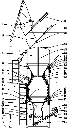
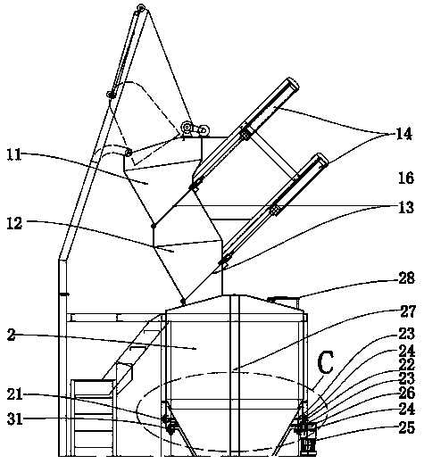
[0041] see Figure 1~Figure 3 , it can be seen from the figure that a composite biomass gasifier includes:

[0042] Furnace base, as the support of the whole composite biomass gasification furnace body;

[0043] The gasification reaction chamber 4 is arranged on the furnace base as a place for gasification reaction of biomass fuel;

[0044] The feed bin 2 is arranged above the gasification reaction chamber 4 as a processing bin for biomass fuel;

[0045] The feed hopper 1 is arranged above the silo 2, and is used for loading biomass fuel and controlling the biomass fuel entering the silo 2;

[0046] The gasification blower 38 is arranged outside the gasification reaction chamber 4 to blow air for the gasification reaction chamber 4;

[0047] Wherein, the silo 2 and the gasification reaction ch...


PUM


Abstract

The invention discloses a composite biomass gasification furnace, which mainly comprises a gasification reaction chamber and a carbon layer gasification chamber for high-temperature reaction to generate fuel gas to form a composite gas. A biomass fuel is firstly subjected to a high-temperature cracking gasification reaction in the gasification reaction chamber to generate the fuel gas, the biomassfuel which is not completely reacted in the gasification reaction chamber is converted into biomass carbon which falls into the carbon layer gasification chamber, and then the high-temperature biomass carbon is subjected to an oxidation reduction reaction with incoming air below and water vapor generated by high temperature in a sealed water tank to generate carbon monoxide and hydrogen, so thatthe biomass fuel is converted into the fuel gas as much as possible. The composite biomass gasification furnace is characterized in that the structure is scientific, ingenious and compact, and a feedhopper with a double-layer structure can prevent the fuel gas from escaping during feeding. A hopper-cone-shaped material pulling disc prevents bridging and arching of a stock bin; a air supply pipe serves as a middle air inlet channel, and air inletting is more uniform without dead angles; a sealed water tank can prevent the fuel gas from leaking during ash discharge; and a slag breaking fire grate is extruded to break coking blocks formed by biomass ash at high temperature.

Description

technical field [0001] The invention relates to a gasification furnace, in particular to a gasification furnace using biomass as biomass fuel, straw, wood chips, garbage and other raw materials as biomass fuel. Background technique [0002] The gasification furnace is a gas preparation equipment that uses biomass as a biomass fuel. In order to solve the common problems of coking and excessive nitrogen oxides in pellet burners used in a large range of biomass-formed biomass fuels, the inventor invented The application number is 2016205519546, the name is "a biomass downdraft gasification and heating system", the application number is 2016205519550, the name is "a biomass gasification gas system and its ash discharge, slag and dust removal system"; the application No. 2016205519531 and a series of patents titled "A New Furnace Core Structure for Medium-to-Large Biomass Gasification Devices". However, there are still some deficiencies in the structure of feed and slag discharg...

Claims


Application Information

Patent Timeline
Patent Type & Authority Applications(China)
IPC IPC(8): C10J3/20C10J3/30C10J3/32C10J3/34C10J3/72C10J3/74C10J3/84
CPCC10J3/20C10J3/30C10J3/32C10J3/34C10J3/72C10J3/721C10J3/725C10J3/74C10J3/84C10J2300/0916C10J2200/152
Inventor 周勇
Owner 周勇
Learn More