Wireless energy transmission system with stable working frequency

A technology of wireless energy transmission and operating frequency, applied in circuit devices, electrical components, etc., can solve the problems of restricting the application of wireless energy transmission system, frequency splitting, and the optimal operating frequency varies greatly, so as to maintain high-efficiency transmission, enhance High efficiency, the effect of suppressing operating frequency splitting

Pending Publication Date: 2019-12-13
SHANXI DATONG UNIV
View PDF3 Cites 0 Cited by
  • Summary
  • Abstract
  • Description
  • Claims
  • Application Information

AI Technical Summary

Problems solved by technology

[0004] The introduction of the resonant structure improves the performance of the wireless energy transmission system, and at the same time, some adverse effects appear. The main performance is that when the two resonant structures are too close, there will be an over-coupling state, resulting in the optimal operating frequency of the system changing greatly with the distance. And when the transmission distance is very small, the phenomenon of frequency splitting occurs, these adverse phenomena seriously limit the flexible and efficient application of wireless energy transmission systems at different distances

Method used


Image

  • Wireless energy transmission system with stable working frequency
  • Wireless energy transmission system with stable working frequency
  • Wireless energy transmission system with stable working frequency

Examples


Embodiment Construction

[0036] The following will clearly and completely describe the technical solutions in the embodiments of the present invention with reference to the accompanying drawings in the embodiments of the present invention. Obviously, the described embodiments are only some, not all, embodiments of the present invention. Based on the embodiments of the present invention, all other embodiments obtained by persons of ordinary skill in the art without making creative efforts belong to the protection scope of the present invention.

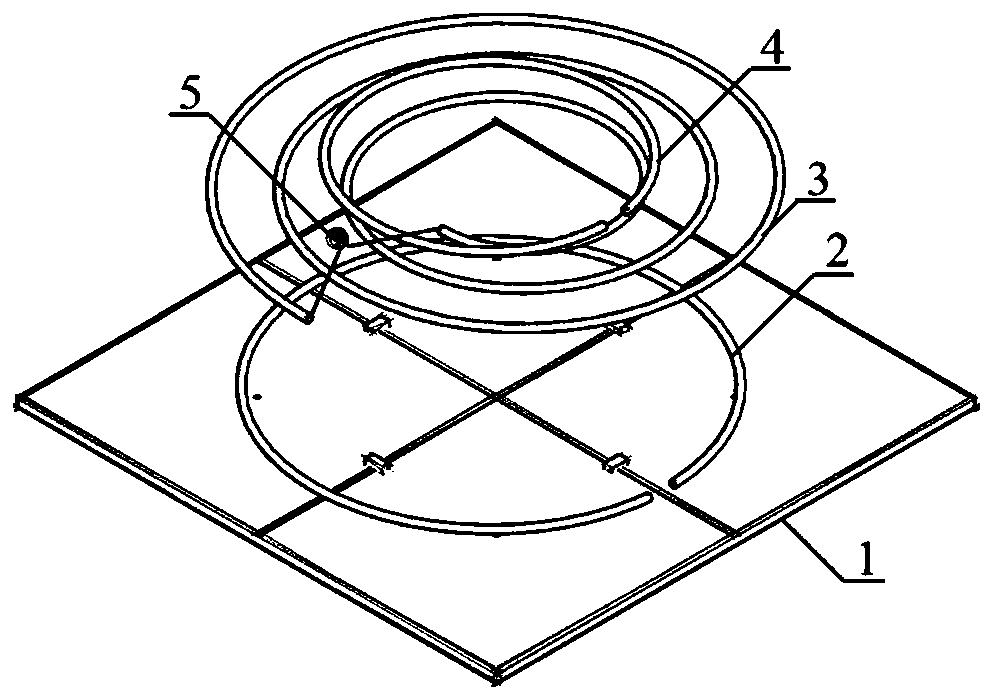
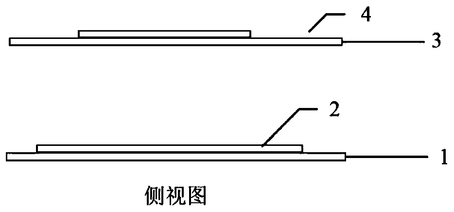
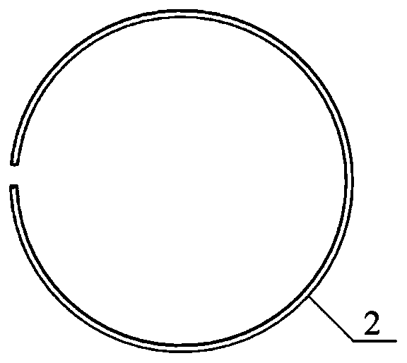
[0037] see Figure 1-Figure 7, a wireless energy transmission system with stable working frequency, including a PCB resonant surface 1, a non-resonant excitation coil 2, a resonant receiving coil 3, a non-resonant load coil 4 and a ceramic capacitor 5, and the PCB resonant surface 1 is sequentially provided with non-resonant The resonant excitation coil 2, the resonant receiving coil 3, the ceramic chip capacitor 5 and the non-resonant load coil 4, the PCB res...


PUM

PropertyMeasurementUnit
Diameteraaaaaaaaaa
Thicknessaaaaaaaaaa
Capacitanceaaaaaaaaaa

Abstract

A wireless energy transmission system with a stable working frequency is disclosed. The system comprises a PCB resonance surface. A non-resonance excitation coil, a resonance receiving coil, a ceramiccapacitor and a non-resonance load coil are successively arranged above the PCB resonance surface. The non-resonance excitation coil, the resonance receiving coil and the non-resonance load coil carry out wireless energy transmission through near magnetic field coupling. The resonance receiving coil is connected with one ceramic capacitor. The PCB resonance surface is composed of a chip capacitor, a top surface square copper patch, a bottom surface large square copper patch, a copper plating hole and a dielectric plate. The chip capacitor is loaded in a gap between two adjacent top surface small square copper patches, the top surface small square copper patches and the bottom surface large square copper patch are connected through the copper plating hole, and bottom surface copper and topsurface copper are bonded on the dielectric plate. The wireless energy transmission system is stable in working frequency, capable of inhibiting working frequency splitting and keeping high-efficiency transmission, and is suitable for non-fixed-distance short-distance wireless energy transmission.

Description

technical field [0001] The invention relates to a wireless energy transmission system, in particular to a wireless energy transmission system with stable working frequency. Background technique [0002] Effective acquisition and efficient and convenient use of energy has always been important. Among them, the introduction of electric energy facilitates the design and application of many energy-consuming devices, and the perfection of the power system ensures the availability of electricity for human beings, which greatly improves the efficiency and convenience of energy use. With the improvement of human technology and civilization, the Internet of Things and artificial intelligence have also begun to enter the upsurge of development. These developments have put forward higher requirements for more efficient and flexible energy supply. One way to meet this requirement is to make energy supply Like a communication network, it is always online, and one way to implement the en...

Claims


Application Information

Patent Timeline
IPC IPC(8): H02J50/12H02J50/70
CPCH02J50/12H02J50/70
Inventor 董丽娟石泰峡陈永强刘艳红邓富胜石云龙
Owner SHANXI DATONG UNIV
Why Eureka
Try Eureka