Highly-efficient drive circuit of light emitting diode (LED) Light Bars

A driving circuit and LED light group technology, which is applied in the direction of electric lamp circuit layout, electric light source, lighting device, etc., can solve the problems of BOOST voltage boosting cost, low efficiency, increased loss, etc., achieve fast current response, improve quality, The effect of increasing reliability

Inactive Publication Date: 2014-04-16
TPV ELECTRONICS (FUJIAN) CO LTD
View PDF7 Cites 0 Cited by
  • Summary
  • Abstract
  • Description
  • Claims
  • Application Information

AI Technical Summary

Problems solved by technology

The BOOST converter in this circuit will increase the loss and reduce the efficiency, and the cost of the BOOST boost voltage is relatively high

Method used


Image

  • Highly-efficient drive circuit of light emitting diode (LED) Light Bars
  • Highly-efficient drive circuit of light emitting diode (LED) Light Bars
  • Highly-efficient drive circuit of light emitting diode (LED) Light Bars

Examples


Embodiment Construction

[0025] The present invention will be further described below in conjunction with the accompanying drawings and embodiments.

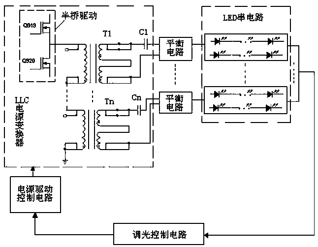
[0026] Please refer to figure 2 , the present embodiment provides a high-efficiency LED Light Bar driving circuit, which includes a half-bridge drive of an LLC power converter, and the output end of the half-bridge drive is connected to a loop composed of an integer number of primary transformers connected in series; each transformer Each of the secondary first ends of the secondary terminals is connected in series with a DC blocking capacitor and supplies power to an LED lamp group through an LED voltage difference balancing circuit. The LED lamp group is composed of a first LED string and a second LED string connected in parallel, and the LED The output end of the lamp group is connected with a dimming control circuit, and the output end of the dimming control circuit is connected with the LLC power converter through a power drive control circuit.

...


PUM


Abstract

The invention relates to a highly-efficient drive circuit of light emitting diode (LED) Light Bars. The drive circuit is characterized by comprising a half-bridge driver of a logical link control (LLC) power converter, wherein the output end of the half-bridge driver is connected with a loop which consists of an integral number of primary serial transformers; and a first end of a secondary winding of each transformer is connected in series with a blocking capacitor and provides power for an LED light set through an LED voltage difference balance circuit, the LED light set is formed by parallelly connecting a first LED string and a second LED string, the output end of the LED light set is connected with a dimming control circuit, and the output end of the dimming control circuit is connected with the LLC power converter through a power drive control circuit. According to the highly-efficient drive circuit of the LED Light Bars, the output of a main power circuit is used for directly driving each LED Light Bar, and the phenomenon that the output of the main power circuit in the conventional framework is required to pass through one stage of direct current / direct current (DC / DC) booster converter at first and then drive each LED light string is avoided.

Description

technical field [0001] The invention relates to an efficient LED Light Bar driving circuit. Background technique [0002] At present, most of the LED Light Bar drive circuits of liquid crystal displays first use the output 12V voltage of the Flyback structure to supply power to the T-CON of the LCD panel. A voltage slightly higher than that of the LED Light Bar is connected to the positive plate of each LED Light Bar string to supply power to the LED Light Bar string; the negative terminal of each LED Light Bar string is connected to a constant current source. [0003] Now, for large-size displays, the working voltage of the LED Light Bar is relatively high, reaching more than 100 volts, and the energy for powering the LED Light Bar is all obtained from a low voltage of 24V through BOOST. Please refer to figure 1 , figure 1 It is an existing LED power supply circuit, which includes a flyback circuit outputting 24V voltage to supply power to an LED string circuit after bei...

Claims


Application Information

Patent Timeline
Patent Type & Authority Patents(China)
IPC IPC(8): H05B37/02
Inventor 王星光庄锦清
Owner TPV ELECTRONICS (FUJIAN) CO LTD
Why Eureka
Try Eureka