
A resistor automatic bushing equipment

A technology for casing equipment and resistors, which is used in the manufacture of encapsulation/casing resistors, etc., can solve the problems of lowering the yield of casings, and achieve the effects of improving the yield and preventing different distances.

Active Publication Date: 2021-05-07
上海芬能自动化技术股份有限公司
View PDF6 Cites 0 Cited by
  • Summary
  • Abstract
  • Description
  • Claims
  • Application Information

AI Technical Summary

Problems solved by technology

[0005] Aiming at the deficiencies in the prior art, the object of the present invention is to provide an automatic casing device for resistors, so as to solve the problems in the prior art when entering the casing at a fixed push-out distance due to the different lengths of the pins at both ends of the resistor. As a result, one end of the resistor is exposed to the outside, while the other end lacks a long sleeve, which results in the sleeve not being completely covered on the outer surface of the resistor, which reduces the yield of the resistor sleeve and requires adjusting the length of the pin. Causes more precise and uniform problems when cutting pins

Method used


Image

  • A resistor automatic bushing equipment
  • A resistor automatic bushing equipment
  • A resistor automatic bushing equipment

Examples


specific Embodiment

[0027] see Figure 1-Figure 9 , the specific embodiments of the present invention are as follows:

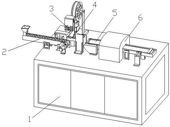
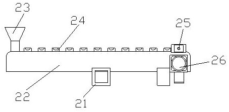
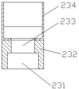
[0028] Its structure includes a chassis 1, a resistor transmission structure 2, a sleeve machine 3, a forming table 4, a conveyor belt 5, and an oven 6. The resistor transmission structure 2 is horizontally installed on the upper end of the chassis 1 and is mechanically connected. The machine 3 is installed vertically on the upper end of the cabinet 1 and is located inside the resistor transmission structure 2, the forming table 4 is located between the resistor transmission structure 2 and the casing machine 3, and the conveyor belt 5 is installed horizontally on the upper end of the cabinet 1 and is located On the right side of the forming table 4, the oven 6 is sleeved on the outside of the conveyor belt 5 and installed on the upper end of the cabinet 1; the resistor transmission structure 2 includes a bracket 21, a casing 22, a resistor positioning structure 23, a resistor c...


PUM


Abstract

The invention discloses an automatic bushing device for resistors. The structure includes a casing, a resistor transmission structure, a casing machine, a forming table, a conveyor belt, and an oven. The resistor transmission structure is horizontally installed on the upper end of the casing, and the casing machine is vertical Installed on the upper end of the chassis, the forming table is located between the resistor transmission structure and the casing machine, the conveyor belt is installed horizontally on the upper end of the chassis, and the oven is set outside the conveyor belt; the resistor transmission structure includes brackets, casings, resistor positioning structures, resistors The inside of the bracket is welded to the outside of the shell, the resistor positioning structure is vertically installed on the upper end of the shell, and the resistor conveyor belt is installed on the inside of the shell. The present invention sets a resistor at the front end of the casing machine Transmission structure, so that the push plate does not touch the pins to push the resistors, preventing the different lengths of the pins from causing different push distances, so that the resistors can be pushed into the casing better, ensuring that the resistors are wrapped in the casing, and improving yield rate.

Description

technical field [0001] The invention belongs to the field of resistor production equipment, and in particular relates to an automatic bushing device for resistors. Background technique [0002] Resistors are called resistances in daily life. They are mainly used to limit the current of the branch. After the production is completed, a casing needs to be put on the outside to better insulate the resistance. In the past Manual packaging is usually used, which is inefficient. With the continuous advancement of technology, the equipment can automatically pack resistors in sleeves, improving work efficiency and reducing labor costs. However, the existing technology has the following shortcomings: [0003] Due to the different lengths of the pins at both ends of the resistor, when a fixed push-out distance enters the sleeve, one end of the resistor will be exposed to the outside, and the other end will lack a longer sleeve, resulting in the sleeve not being completely covered with ...

Claims


Application Information

Patent Timeline
Patent Type & Authority Patents(China)
IPC IPC(8): H01C17/02
CPCH01C17/02
Inventor 陈丽娟
Owner 上海芬能自动化技术股份有限公司
Learn More