
Anti-oxidation powder metallurgy hydraulic forming machine

A technology of powder metallurgy and forming machine, which is applied in the field of anti-oxidation powder metallurgy hydraulic forming machine, which can solve the problems of insufficient workpiece strength, product quality not meeting the requirements, powder oxidation, etc.

Inactive Publication Date: 2020-12-04
泉州市良创信息科技有限公司
View PDF0 Cites 0 Cited by
  • Summary
  • Abstract
  • Description
  • Claims
  • Application Information

AI Technical Summary

Problems solved by technology

[0003] However, when the powder metallurgy hydraulic molding machine is in use, the powder will be in contact with the air during the extrusion molding process of the oxidized powder, causing the powder to oxidize. At the same time, the workpiece that needs to be moved into the sintering furnace will be oxidized The workpiece will cause insufficient strength of the workpiece, so that the quality of the product cannot meet the requirements

Method used


Image

  • Anti-oxidation powder metallurgy hydraulic forming machine
  • Anti-oxidation powder metallurgy hydraulic forming machine
  • Anti-oxidation powder metallurgy hydraulic forming machine

Examples


Embodiment 1

[0027] Such as figure 1 As shown, an anti-oxidation powder metallurgy hydraulic molding machine includes a rotating cover 1 and a sintering furnace 12, the front end of the sintering furnace 12 is hinged to the rotating cover 1, and the upper end of the sintering furnace 12 is welded and fixedly connected to a support frame 6 , the upper end face of the support frame 6 is connected with a hydraulic cylinder 7, the lower end face of the hydraulic cylinder 7 is connected with a telescopic rod 5 at the inner position of the support frame 6, and the lower end face of the telescopic rod 5 is connected with an upper shaping device 9, and the upper end face of the telescopic rod 5 is connected with an upper shaping device 9. The lower end face of the device 9 is connected with a lifting rod 8, the lower end face of the lifting rod 8 is connected with a limiting device 10, the lower end face of the limiting device 10 is connected with a positioning rod 11, and the lower end of the limi...

Embodiment 2

[0030] Such as Figure 1-3 As shown, an anti-oxidation powder metallurgy hydraulic molding machine includes a rotating cover 1 and a sintering furnace 12, the front end of the sintering furnace 12 is hinged to the rotating cover 1, and the upper end of the sintering furnace 12 is welded and fixedly connected to a support frame 6 , the upper end face of the support frame 6 is connected with a hydraulic cylinder 7, the lower end face of the hydraulic cylinder 7 is connected with a telescopic rod 5 at the inner position of the support frame 6, and the lower end face of the telescopic rod 5 is connected with an upper shaping device 9, and the upper end face of the telescopic rod 5 is connected with an upper shaping device 9. The lower end face of the device 9 is connected with a lifting rod 8, the lower end face of the lifting rod 8 is connected with a limiting device 10, the lower end face of the limiting device 10 is connected with a positioning rod 11, and the lower end of the l...

Embodiment 3

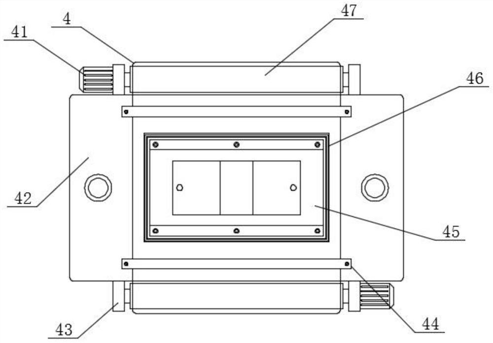
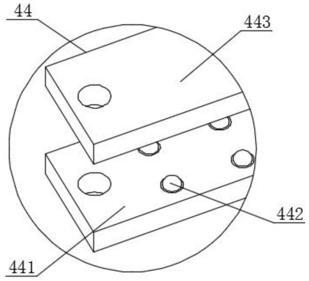
[0033] Such as Figure 1-4 As shown, an anti-oxidation powder metallurgy hydraulic molding machine includes a rotating cover 1 and a sintering furnace 12, the front end of the sintering furnace 12 is hinged to the rotating cover 1, and the upper end of the sintering furnace 12 is welded and fixedly connected to a support frame 6 , the upper end face of the support frame 6 is connected with a hydraulic cylinder 7, the lower end face of the hydraulic cylinder 7 is connected with a telescopic rod 5 at the inner position of the support frame 6, and the lower end face of the telescopic rod 5 is connected with an upper shaping device 9, and the upper end face of the telescopic rod 5 is connected with an upper shaping device 9. The lower end face of the device 9 is connected with a lifting rod 8, the lower end face of the lifting rod 8 is connected with a limiting device 10, the lower end face of the limiting device 10 is connected with a positioning rod 11, and the lower end of the l...


PUM


Abstract

The invention provides an anti-oxidation powder metallurgy hydraulic forming machine. The anti-oxidation powder metallurgy hydraulic forming machine is characterized in that a rotating cover is connected to the front end face of a sintering furnace through a hinge, a supporting frame is fixedly connected to the upper end face of the sintering furnace in a welded mode, a hydraulic cylinder is connected to the upper end face of the supporting frame, a telescopic rod is connected to the position, in the supporting frame, of the lower end face of the hydraulic cylinder, an upper shaping device isconnected to the lower end face of the telescopic rod, and a lifting rod is connected to the lower end face of the upper shaping device in a penetrating mode. According to the anti-oxidation powder metallurgy hydraulic forming machine, a lower shaping device composed of a power motor, a shaping plate, a winding device, a sliding device, a lower shaping mold, a cutter groove and a rotating wheel isarranged, the rotating wheel can be well driven by using the power motor to rotate, and the rotating wheel rotates to be matched with the winding device so that a continuous film can be well placed on the surface of the lower shaping mold; and meanwhile, the thin film can be well cut through the cutter groove and a cutter, and it is guaranteed that the thin film can be well wrapped around the surface of a formed workpiece.

Description

technical field [0001] The invention relates to the field of industrial machinery, in particular to an anti-oxidation powder metallurgy hydraulic forming machine. Background technique [0002] Metal injection molding is a new type of powder metallurgy near-net forming technology derived from the plastic injection molding industry. As we all know, plastic injection molding technology can produce products with various complex shapes at a low price, but the strength of plastic products is not high. In order to improve its properties, metal or ceramic powders can be added to plastics to obtain products with higher strength and good wear resistance. In recent years, this idea has evolved to maximize the content of solid particles and completely Removing the binder and densifying the formed blank, this new powder metallurgy forming method is called metal injection molding, and the powder metallurgy hydraulic forming machine uses a hydraulic device to press the powder into a workpi...

Claims


Application Information

Patent Timeline
Patent Type & Authority Applications(China)
IPC IPC(8): B22F3/22B22F3/00
CPCB22F3/003B22F3/225
Inventor 戴景华何锋锋
Owner 泉州市良创信息科技有限公司
Learn More