Ion beam irradiation device

A technology of irradiation device and ion beam, which is applied to irradiation devices, discharge tubes, electrical components, etc., can solve the problems of measurement error, cost, complicated driving mechanism design, etc., and achieve the effect of preventing false measurement and simplifying design.

Active Publication Date: 2019-12-10
NISSIN ION EQUIP CO LTD
View PDF9 Cites 0 Cited by
  • Summary
  • Abstract
  • Description
  • Claims
  • Application Information

AI Technical Summary

Problems solved by technology

[0004] When the above-mentioned suppression electrode is installed on the movable Faraday cup, it is necessary to consider the winding of the electrical wiring used to energize the suppression electrode or the weight of the suppression electrode, and the design of the driving mechanism becomes complicated.
In addition, there is also the cost of the part where the suppression electrode is provided
On the other hand, if the suppression electrode is not provided, the mechanism for pushing the secondary electrons released from the cup part back to the cup side will disappear, resulting in measurement errors

Method used


Image

  • Ion beam irradiation device
  • Ion beam irradiation device
  • Ion beam irradiation device

Examples


Embodiment Construction

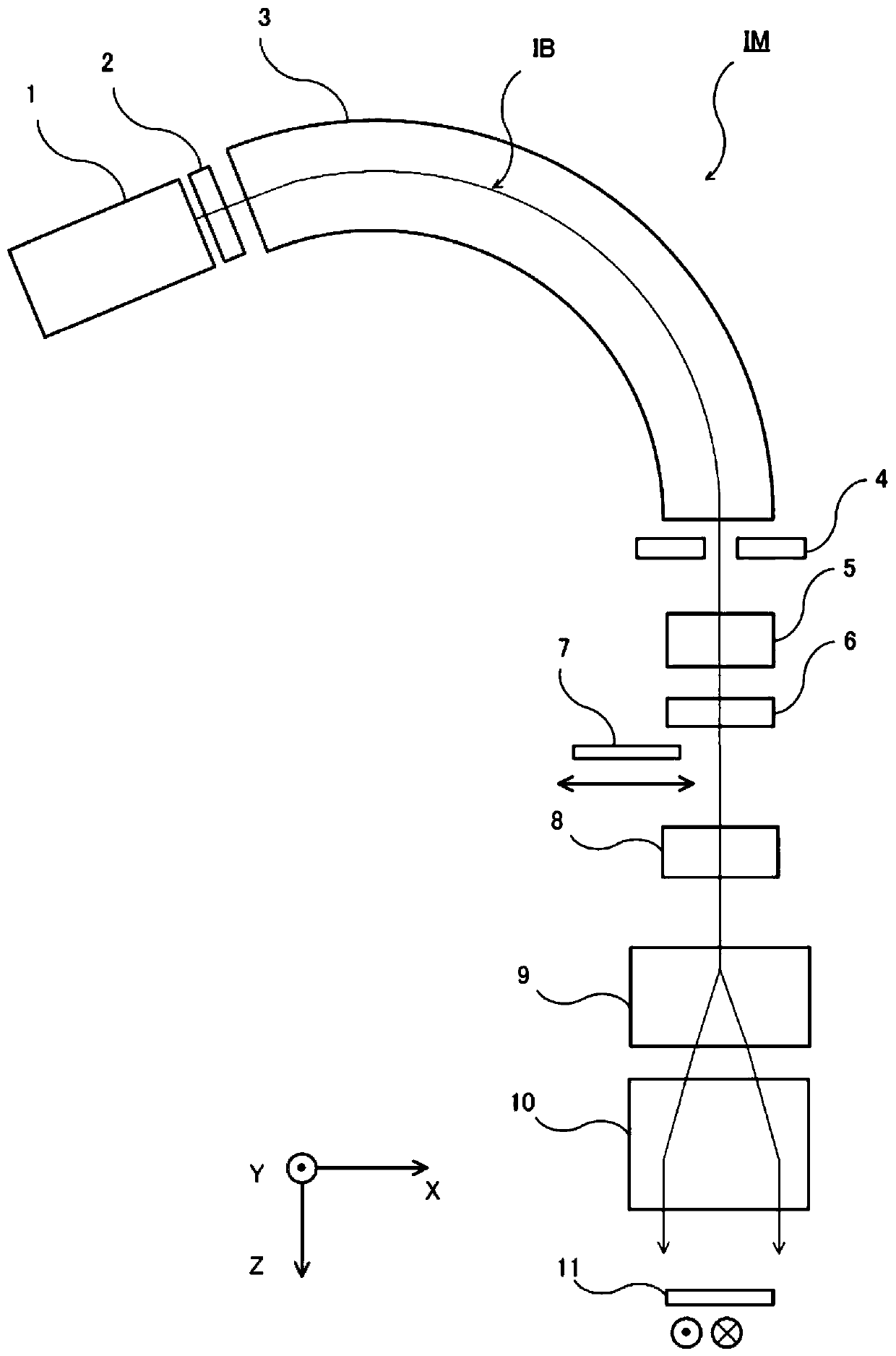
[0036] figure 1 It is a schematic plan view which shows the whole of ion beam irradiation apparatus IM. exist figure 1 In the above, the description will be given based on the configuration example of the ion implantation device, but as the ion beam irradiation device to which the present invention is applied, an ion implantation device, an ion beam etching device, an ion beam surface modification device, etc. equipped with a beam transporting ion beam can be conceived. Devices for conveying paths.

[0037] The directions of the illustrated XYZ axes are drawn with reference to the ion beam irradiated on the target 11 . The Z direction is the traveling direction of the ion beam, and the X direction is the scanning direction of the scanner 9 described later. The Y direction is a direction perpendicular to both directions of the X direction and the Z direction. In addition, the illustrated beam trajectory IB of the ion beam indicates the center trajectory of the ion species i...


PUM


Abstract

The present invention relates to an ion beam irradiation device which simplifies the design of a drive mechanism in a movable beam current meter (7) and can gradually return secondary electrons emitted from a beam measurement site. This ion beam irradiation device (IM) is provided with: a beam current measurement device (7) that can measure a beam current by passing in and out of a beam path (IB);and a first electrode (6) that is disposed on the beam transport path immediately before reaching the beam current meter (7). The first electrode (6) is also provided with: a suppression electrode that returns the secondary electrons emitted from the beam current meter (7) back to the beam current meter side; and another beam optical member.

Description

technical field [0001] The present invention relates to an ion beam irradiation device including a movable beam current measuring device. Background technique [0002] In the ion beam irradiation apparatus, a movable Faraday cup (also referred to as a beam current measuring device) described in Patent Document 1 is used. This Faraday cup enters and exits the beam track on the downstream side of the mass analysis electromagnet, and is used to measure the mass spectrum of the ion species contained in the mass analysis ion beam, and adjusts the magnetic field of the mass analysis electromagnet so that the desired The beam current of the ion species becomes maximum. [0003] In addition to the part of the cup where the beam current is measured, the Faraday cup is equipped with a suppressing electrode, and a negative voltage is applied to the suppressing electrode to push the secondary electrons released from the cup described in Patent Document 2 back to the cup side. . With ...

Claims


Application Information

Patent Timeline
Patent Type & Authority Applications(China)
IPC IPC(8): H01J37/30H01J37/244G21K5/04
CPCG21K5/04H01J37/3007H01J37/244H01J2237/24564H01J2237/24535H01J37/30H01J2237/31701H01J2237/004H01J2237/028H01J2237/24405H01J37/05H01J2237/055H01J2237/057H01J2237/047
Inventor 山元彻朗
Owner NISSIN ION EQUIP CO LTD
Why Eureka
Try Eureka