Optical disc device
An optical disc device, optical disc technology, applied in the directions of configuration/installation of heads, recording/reproducing by optical methods, instruments, etc., can solve the problem of increased circuit scale, no data recorded on optical discs, and inability to perform focus balance adjustment using playback signals and other problems, to achieve the effect of simple structure, focus balance adjustment, and cost reduction
- Summary
- Abstract
- Description
- Claims
- Application Information
AI Technical Summary
Problems solved by technology
Method used
Image

Examples
no. 1 example
[0040] First, an optical disc device according to a first embodiment of the present invention will be described with reference to the drawings.
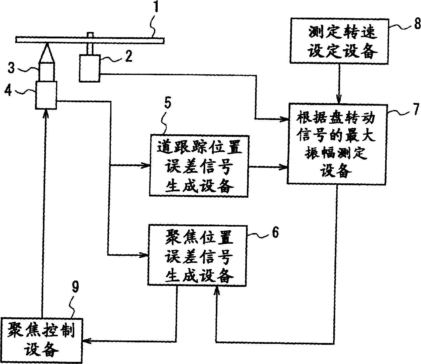
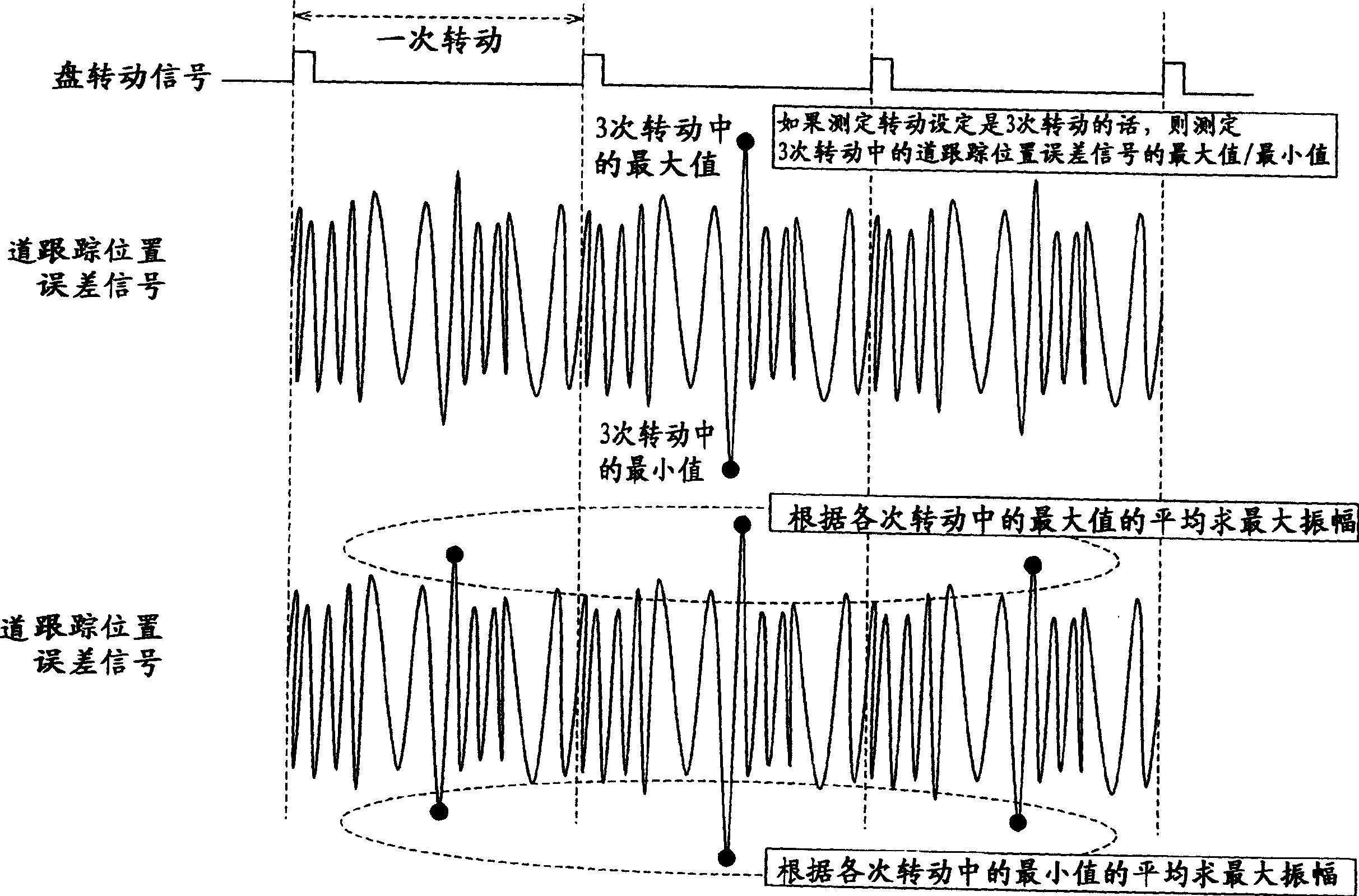
[0041] figure 1 A configuration example of the optical disc device according to the first embodiment of the present invention is shown. exist figure 1 Among them, 1 is a disc, 2 is a spindle motor for rotating the disc 1, 3 is a wave picker for reading and writing information on the surface of the disc 1, 4 is a photodetector for detecting the signal of the optical pickup 3, and 5 is an optical pickup. The track tracking position error signal generation device that generates the error signal of the track tracking position based on the signal of the detector 4, and the focus position 6 that generates the error signal of the focus position of the optical pickup 3 based on the signal of the photodetector 4 The error signal generation device, 7 is the maximum amplitude measurement device based on the disc rotation signal for measuring ...
no. 2 example
[0053] Next, an optical disc device according to a second embodiment of the present invention will be described with reference to the drawings.
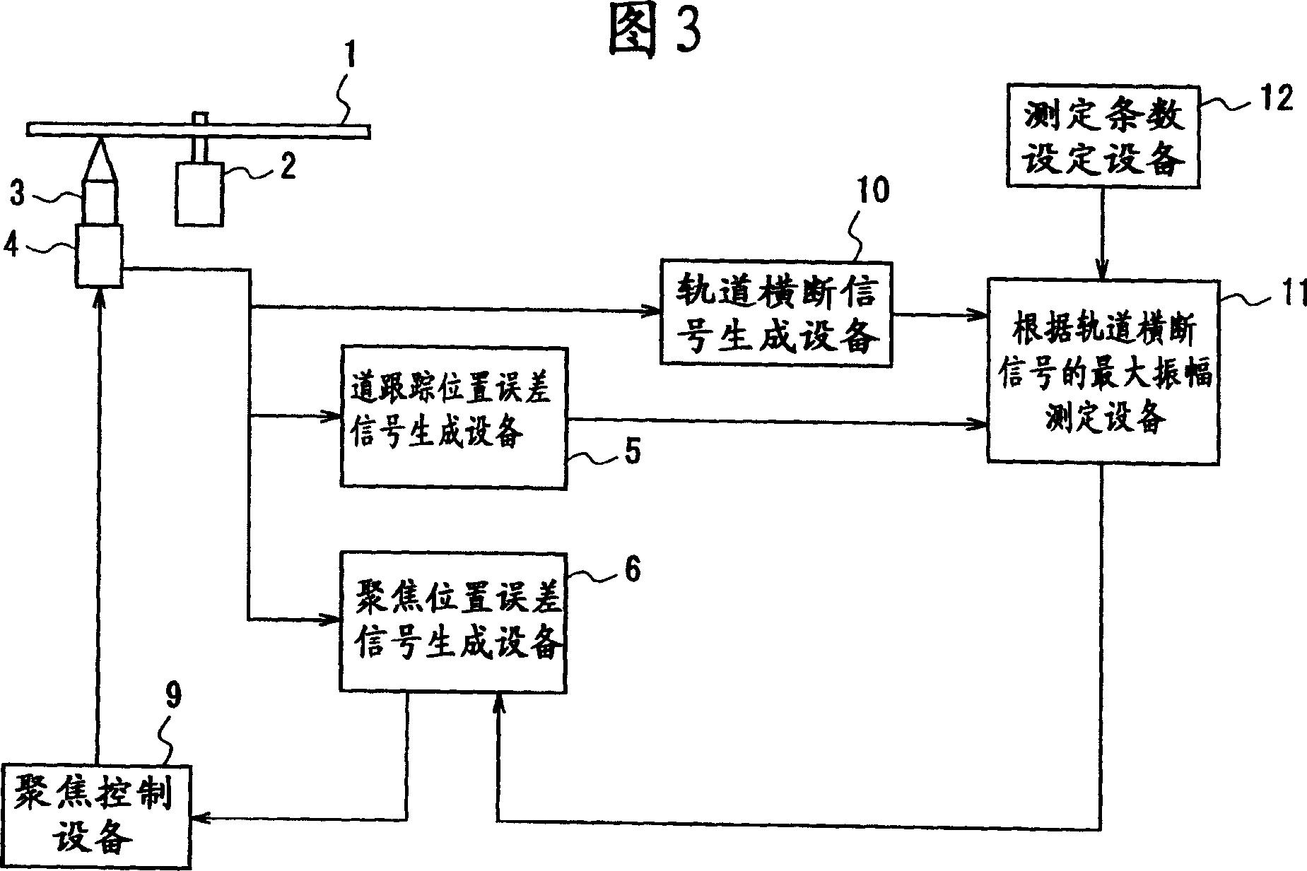
[0054] FIG. 3 shows a configuration example of an optical disc device according to the second embodiment. In FIG. 3, the figure 1 The same symbols represent the same or equivalent parts, and figure 1 The difference of the shown structure is that a track crossing signal generation device 10 that generates a track crossing signal based on the signal from the photodetector 4 is newly installed; The maximum amplitude measuring device 11 of the maximum amplitude;
[0055] In this embodiment, the measurement of the maximum amplitude of the track tracking position error signal is performed as in the first embodiment, but it is different from the first embodiment in that a track crossing signal generated by reflected light passing through the track is used.
[0056] Specifically, if the focal point toward the disk is matched even if the ac...
no. 3 example
[0064] Next, an optical disc device according to a third embodiment of the present invention will be described with reference to the drawings.
[0065] Figure 5 shows an example of the configuration of the optical disc device according to the third embodiment, in Figure 5 3, the same symbols as in FIG. 3 denote the same or equivalent parts. The difference from the second embodiment shown in FIG. Whether the frequency of the signal is within the frequency range set by the frequency setting device 14 is used to detect the frequency detection device 13, and the frequency detection signal obtained by using the frequency detection device 13 is input to the maximum amplitude measuring device 15 based on the frequency detection signal.
[0066] In this third embodiment, the measurement of the maximum amplitude of the track tracking position error signal is performed as in the above-mentioned embodiments, but it is different from the embodiments in that the frequency of the track c...
PUM
 Abstract
Description
Claims
Application Information
 - Generate Ideas
- Intellectual Property
- Life Sciences
- Materials
- Tech Scout
- Unparalleled Data Quality
- Higher Quality Content
- 60% Fewer Hallucinations
Browse by: Latest US Patents, China's latest patents, Technical Efficacy Thesaurus, Application Domain, Technology Topic, Popular Technical Reports.
© 2025 PatSnap. All rights reserved.Legal|Privacy policy|Modern Slavery Act Transparency Statement|Sitemap|About US| Contact US: help@patsnap.com