
Manufacturing process of a steel-concrete composite beam bridge joint structure

A production process and concrete technology, applied in the direction of bridges, bridge materials, bridge construction, etc., can solve the problems of large impact on site construction environment, large welding workload, reduced joint reliability, etc., to improve the longitudinal shear capacity, The effect of alleviating fatigue damage and improving reliability

Active Publication Date: 2021-04-13
ZHEJIANG INST OF COMM
View PDF8 Cites 0 Cited by
  • Summary
  • Abstract
  • Description
  • Claims
  • Application Information

AI Technical Summary

Problems solved by technology

At present, the commonly used bridge deck longitudinal seam connection structure mostly adopts the method of prefabricated bridge deck overhanging reinforcement and pouring concrete with the same label as the prefabricated bridge deck, which has many potential safety hazards: (1) The prefabricated bridge deck overhanging reinforcement is only tied or If it is not treated, the reliability of the joint will be greatly reduced. If the welding process is adopted, the welding workload on site will be huge, and it will be greatly affected by the construction environment on site; The concrete, prefabricated steel bars and concrete are jointly stressed. In general, the shear force and negative bending moment at the joint between the old and new concrete are often large. The old and new concrete are under reciprocating loads for a long time, and they are prone to peeling off from each other. (3) The traditional joint technology often does not set longitudinally distributed structural reinforcement at the joint section. Under the action of vehicle load, the upper and lower parts of the upper joint of the steel beam respond to reciprocating compression loads, and the prefabricated steel bars appear. In-plane and out-of-plane bending, causing local crushing, this kind of damage will have a fatal impact on the normal service of steel-concrete composite beams, and the durability of the bridge cannot be guaranteed; (4) The shear resistance of traditional jointing technology Connectors are generally connected to steel beams by welding. When the joints are completed, the concrete and steel beams are prone to peeling off under the action of external loads. The interface between the steel beam and concrete is the shear connector and the steel beam. The welded part is prone to corrosion fatigue damage under the action of external load and external humid environment, thereby reducing the reliability of the connection between the steel beam and the concrete slab; It is clearly stipulated that "when the bridge deck uses prefabricated reinforced concrete bridge deck, measures should be taken to make the prefabricated concrete slab and steel girder closely bonded to meet the waterproof requirements", and "JTG / T D64-01 -2015" on the durability design of the steel-concrete contact surface also stipulates that "the contact surface should be prevented from being hollowed out from the aspects of concrete configuration, structural requirements, and construction technology." The requirement of tightness and no gap between concrete slabs cannot be achieved

Method used


Image

  • Manufacturing process of a steel-concrete composite beam bridge joint structure
  • Manufacturing process of a steel-concrete composite beam bridge joint structure
  • Manufacturing process of a steel-concrete composite beam bridge joint structure

Examples


Embodiment Construction

[0064] Below in conjunction with accompanying drawing, the utility model is further described.

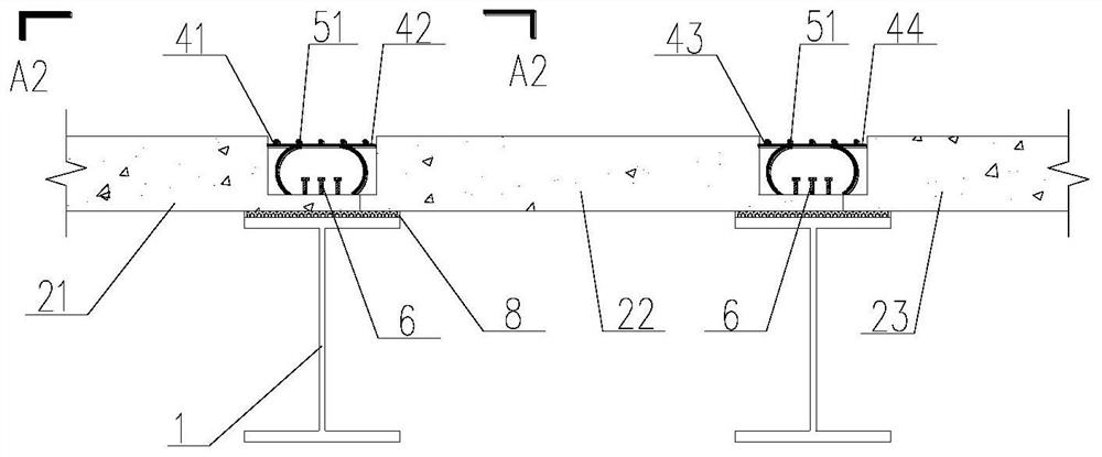
[0065] refer to Figure 1 to Figure 13 , a steel-concrete composite beam bridge joint structure, comprising a steel beam 1, a left precast concrete slab 21, an upper longitudinal reinforcement 211, an upper transverse reinforcement 212, a lower longitudinal reinforcement 213, a lower transverse reinforcement 214, a middle prefabricated Concrete slab 22, upper longitudinal reinforcing bar 221, upper transverse reinforcing bar 2 222, lower longitudinal reinforcing bar 2 223, lower transverse reinforcing bar 2 224, right precast concrete slab 23, epoxy mortar 3, left transverse connecting reinforcing bar 41, middle transverse connecting reinforcing bar 1 42. Middle horizontal connection reinforcement 2 43, right horizontal connection reinforcement 44, upper longitudinal reinforcement 51, lower longitudinal reinforcement 52, shear connector 6, left connection structure 71, left connect...


PUM


Abstract

A manufacturing process for a steel-concrete composite beam bridge joint structure, comprising the following steps: 1) factory prefabrication; 2) on-site assembly as follows: 2.1) transporting the prefabricated steel beams and concrete slabs to the site; 2.2) erecting the steel beams on 2.3) The precast concrete slab is installed on the steel beam by hoisting, and the precast concrete slab is in direct contact with the limiting positioning device; 2.4) The precast concrete slab is initially connected according to the jagged connection length structure extending outward; 2.5) Bind the extended transverse connecting reinforcement of the prefabricated slab to the lower longitudinal reinforcing bar exposed at the connecting short structure of another prefabricated slab, and arrange and bind the upper transverse reinforcing bars above the transverse connecting reinforcement; Epoxy mortar is poured into the joints formed between the boards; 2.7) After solidification, the joints are completed. The invention improves the durability of the composite girder bridge, the shear resistance between steel and concrete, and the bearing capacity of the seam at the fabrication place.

Description

technical field [0001] The invention relates to the architectural details of bridge engineering and its structure and construction fields, in particular to a manufacturing process of a steel-concrete composite beam bridge joint structure. Background technique [0002] In recent years, with the development of my country's economy, the country has paid more and more attention to the research and development and promotion of composite structures. As a structural system with novel structure and excellent mechanical performance, steel-concrete composite beam bridges have been widely used in practical projects. Steel-concrete composite girder bridges set shear connectors between the lower steel girder and the upper concrete flange slab to resist the lifting and relative sliding of the two at the interface, making the two as a whole Working together, the mechanical properties, overall performance and seismic performance of the combined steel plate and concrete bridge deck exceed th...

Claims


Application Information

Patent Timeline
Patent Type & Authority Patents(China)
IPC IPC(8): E01D19/06E01D2/00E01D101/26
CPCE01D2/00E01D19/06E01D2101/26
Inventor 杭振园陈凯陆森强赵伟
Owner ZHEJIANG INST OF COMM
Learn More