A chemical vapor deposition system, gas supply device and gas supply method
A technology of chemical vapor deposition and gas supply equipment, which is applied in pipeline systems, gas/liquid distribution and storage, mechanical equipment, etc., and can solve problems affecting product performance, unstable gas supply, and low saturated steam
- Summary
- Abstract
- Description
- Claims
- Application Information
AI Technical Summary
Problems solved by technology
Method used
Image

Examples
Embodiment 1
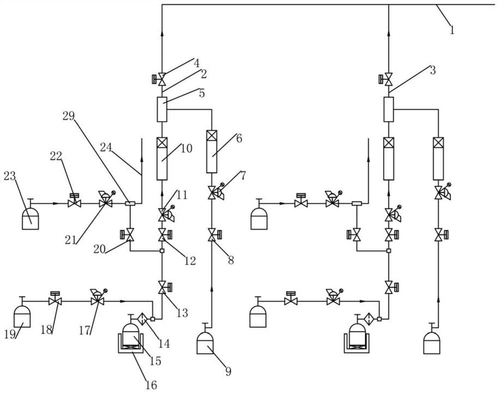
[0041] A gas supply device of a chemical vapor deposition system as an embodiment of the present invention, such as figure 1 As shown, the gas supply device includes a terminal main pipe 1, a first gas supply pipeline 2 and a spare gas supply pipeline 3;
[0042] The terminal main pipe 1 is connected with the vacuum furnace body pipeline of the chemical vapor deposition system, the terminal main pipe 1 is connected with the first gas supply pipeline 2 pipelines, and the terminal main pipe 1 is connected with the standby gas supply pipeline 3 pipelines;
[0043] The first gas supply line 2 includes a mixed gas supply branch line, a process gas supply branch line, a gas mixing tank 5 and a sixth electromagnetic pneumatic valve 4, the mixed gas supply branch line communicates with the gas mixing tank 5, and the process gas supply branch line It communicates with the gas mixing tank 5, and the sixth electromagnetic pneumatic valve 4 is connected between the gas mixing tank 4 and t...
Embodiment 2
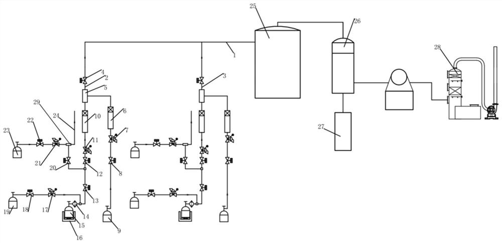
[0054] As a kind of chemical vapor deposition system of the embodiment of the present invention, such as figure 1 As shown, the chemical vapor deposition system includes the gas supply device of the chemical vapor deposition system described in Embodiment 1, a vacuum furnace body 25 communicated with the gas supply device pipeline, a filter 26, a spray tower 28 and Dust collection bucket 27;
[0055] The vacuum furnace body 25 is provided with an exhaust port, the exhaust port communicates with the filter 26 pipeline, the filter 26 communicates with the spray tower 28 pipeline, and the filter 26 communicates with the dust collection bucket 27 .
Embodiment 3
[0057] As a gas supply method for a chemical vapor deposition system according to an embodiment of the present invention, the method includes the following steps:
[0058] (1) install the chemical vapor deposition system as described in embodiment 2;
[0059] (2) Close the fifth electromagnetic pneumatic valve, open the second electromagnetic pneumatic valve, the second pressure transmitter, the first electromagnetic pneumatic valve, the first pressure transmitter, and the fourth electromagnetic pneumatic valve, and close the third electromagnetic pneumatic valve , outputting the gas in the first purge gas storage container for purging;
[0060] (3) Close the first electromagnetic pneumatic valve, open the third electromagnetic pneumatic valve, and output the gas in the second purge gas storage container for purging;
[0061] (4) Repeat step (2) and step (3) 50 times in turn;
[0062] (5) Turn on the vacuum pump of the vacuum furnace body for vacuuming, close the third elect...
PUM
 Abstract
Description
Claims
Application Information
 - R&D
- Intellectual Property
- Life Sciences
- Materials
- Tech Scout
- Unparalleled Data Quality
- Higher Quality Content
- 60% Fewer Hallucinations
Browse by: Latest US Patents, China's latest patents, Technical Efficacy Thesaurus, Application Domain, Technology Topic, Popular Technical Reports.
© 2025 PatSnap. All rights reserved.Legal|Privacy policy|Modern Slavery Act Transparency Statement|Sitemap|About US| Contact US: help@patsnap.com