Jitter control method of laser inertial measurement unit

A laser and inertial group technology, applied in measurement devices, instruments, etc., can solve problems such as inability to use rate offset mode, affecting navigation accuracy, abnormal gyro output, etc., to improve test efficiency and automation, improve alignment accuracy, The effect of improving performance indicators

Active Publication Date: 2021-01-29
BEIJING AEROSPACE ERA LASER NAVIGATION TECH CO LTD
View PDF13 Cites 0 Cited by
  • Summary
  • Abstract
  • Description
  • Claims
  • Application Information

AI Technical Summary

Problems solved by technology

The rate bias frequency method cannot be used in the inertial group to realize the navigation function, and it is necessary to quickly and effectively switch to the mechanical jitter method, otherwise the gyro output is abnormal and the navigation accuracy will be affected

Method used


Image

  • Jitter control method of laser inertial measurement unit
  • Jitter control method of laser inertial measurement unit
  • Jitter control method of laser inertial measurement unit

Examples


Embodiment Construction

[0039] The technical solutions of the present invention will be described in further detail below with reference to the accompanying drawings and embodiments.

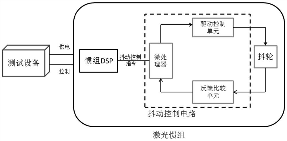
[0040] Such as figure 1 As shown, the jitter control device of the laser inertial group of the present invention includes a test device, a power supply cable and a control cable, an inertial DSP, and a jitter control circuit of the inertial group. The inertial group jitter control circuit includes a microprocessor, a drive control unit and a feedback comparison unit.

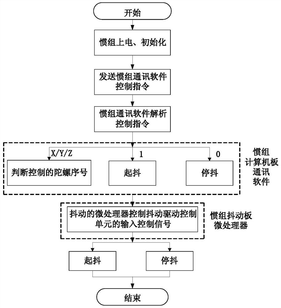
[0041] The specific content of the jitter control method of the present invention is as follows:

[0042] (1) Design the laser inertial group communication protocol:

[0043] The present invention preferably adopts the 1553B bus communication protocol, which includes a jitter control word (unsigned short), a gyroscope serial number (unsigned short), a level flag (unsigned short) and a check word (unsigned short), and the check method adopts CRC16 check...


PUM


Abstract

The invention discloses a jitter control method of a laser inertial measurement unit. The method comprises the following steps: (1) a laser inertial measurement unit communication protocol is designed; (2) test equipment sends a control instruction to inertial measurement unit communication software; (3) the inertial measurement unit communication software sends a control instruction to a jitter control circuit according to the received control instruction; (4) a microprocessor of the jitter control circuit judges the gyro serial number and the jitter control content according to the control instruction of the inertial measurement unit communication software; and (5) the microprocessor of the jitter control circuit realizes the independent jitter control of three gyroscopes by controllingthe on-off of jitter control signals of three drive control units. By sending a jitter control instruction to the laser inertial measurement unit communication software, the independent control over the online jitter of three laser gyroscopes is achieved, and the online switching of different jitter methods of the gyroscope is achieved.

Description

technical field [0001] The invention relates to a vibration control method of a laser inertial group, which is particularly suitable for the gyro vibration control and test of the laser inertial group based on the combination of rate bias frequency and mechanical vibration. Background technique [0002] As a key component in the field of inertial navigation, the laser inertial group usually consists of three orthogonal laser gyros and related control circuits, computer boards and communication software. Laser gyro related control circuits include dithering, frequency stabilization, high voltage and other circuits. The laser gyroscope (RGL) is an important inertial sensitive component of the laser inertial group. It measures the angular velocity of the carrier through the resonance frequency difference between the two-way traveling waves in the ring laser resonator. It is proportional to the angular rate of rotation of the body relative to the inertial space. Lock-up effect...

Claims


Application Information

Patent Timeline
Patent Type & Authority Applications(China)
IPC IPC(8): G01C25/00
CPCG01C25/005Y02P90/02
Inventor 曲丹丹赵兴法陆煜明宋腾腾黄江波任强富
Owner BEIJING AEROSPACE ERA LASER NAVIGATION TECH CO LTD
Why Eureka
Try Eureka