
A Broadband Transition Structure from Ridge-Gap Waveguide to Microstrip Line Based on Probe Current Coupling

A technology of gap waveguide and microstrip line, which is applied in the field of microwave/millimeter wave passive devices, can solve problems such as excessive loss, low assembly tolerance performance, and limited bandwidth, and achieve low insertion loss, high tolerance performance, The effect of high compactness and integration

Active Publication Date: 2021-08-06
UNIV OF ELECTRONICS SCI & TECH OF CHINA
View PDF5 Cites 0 Cited by
  • Summary
  • Abstract
  • Description
  • Claims
  • Application Information

AI Technical Summary

Problems solved by technology

[0004] In order to solve the problems of limited bandwidth, excessive loss, and low assembly tolerance performance faced by ridge-gap waveguides when integrating with MMIC circuits

Method used


Image

  • A Broadband Transition Structure from Ridge-Gap Waveguide to Microstrip Line Based on Probe Current Coupling
  • A Broadband Transition Structure from Ridge-Gap Waveguide to Microstrip Line Based on Probe Current Coupling
  • A Broadband Transition Structure from Ridge-Gap Waveguide to Microstrip Line Based on Probe Current Coupling

Examples


Embodiment Construction

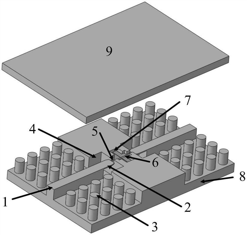
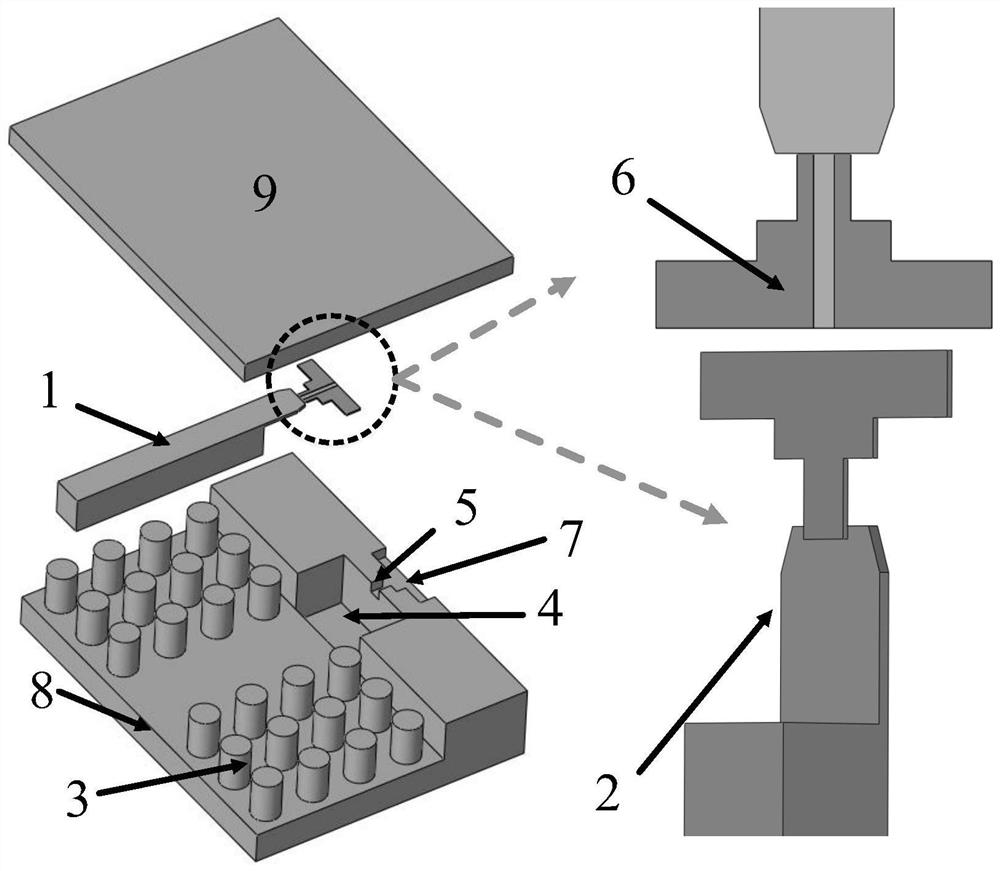
[0032] Taking a transition structure from a ridge-gap waveguide to a microstrip line working in the three bands of C, X, and Ku as an example, the technical solution proposed by the present invention will be further described in detail. The transition structure as a whole is as figure 1 , 2 shown. Includes: ridge-gap waveguide input 1, quarter-wavelength end-cut ridge probe 2, electromagnetic bandgap (EBG) structure 3, terminated short circuit cavity 4, probe and microstrip interconnect window 5, 50 ohm micro Strip line (Rogers 5880 substrate) 6, MMIC installation cavity 7, lower cavity 8 and upper cover 9.

[0033] From the ridge-gap waveguide to the microstrip transition structure, the microwave signal is input from the ridge-gap waveguide in the form of a quasi-TEM mode, and the electromagnetic energy is transmitted to the terminal short-circuit cavity through the ridge probe, and the ridge-gap waveguide and 50 Impedance transformation between ohmic microstrip lines, fol...


PUM


Abstract

The invention discloses a probe current coupling based ridge gap waveguide to microstrip line broadband transition structure, which relates to the field of microwave / millimeter wave passive devices, specifically a probe current coupling based ridge gap waveguide to microstrip line Broadband transition structure. In order to solve the problems of limited bandwidth, excessive loss, and low assembly tolerance performance faced by the ridge-gap waveguide in the prior art when it is integrated with an MMIC circuit. The invention proposes a probe-current-coupled ridge-gap waveguide-to-microstrip broadband transition structure, which has the advantages of ultra-broadband, low loss, strong tolerance performance, compact structure, and easy processing and assembly.

Description

technical field [0001] The invention relates to the field of microwave / millimeter wave passive devices, in particular to a probe current coupling-based ridge-gap waveguide-to-microstrip broadband transition structure. Background technique [0002] In recent years, the low-frequency communication spectrum has been very crowded. In order to meet the current needs of high-speed wireless communication and broadband signal transmission, spectrum resources have to be extended to higher frequency bands. In the millimeter wave frequency band, reducing circuit loss and radiation loss is the primary consideration. Traditional planar transmission lines such as microstrip lines, coplanar waveguides, and striplines are greatly reduced in application value due to a sharp increase in dielectric loss at high frequencies. The new ridge-gap waveguide is a transmission line that is very suitable for working in the millimeter wave band, and it can be used to make passive devices such as passiv...

Claims


Application Information

Patent Timeline
Patent Type & Authority Patents(China)
IPC IPC(8): H01P5/107
CPCH01P5/107
Inventor 蒲友雷彭松涛吴泽威蒋伟王建勋罗勇
Owner UNIV OF ELECTRONICS SCI & TECH OF CHINA
Learn More