
Paper cup cover forming machine station layout structure

A technology of molding and working stations, which is applied in the direction of cardboard items, etc., can solve the problems of spilled drinks in the cup, long production cycle, and low production efficiency, and achieve anti-falling and anti-leakage effects, good temperature uniformity, and low labor costs. low effect

Active Publication Date: 2019-11-26
RUIAN MINGGUO MACHINERY CO LTD
View PDF10 Cites 3 Cited by
  • Summary
  • Abstract
  • Description
  • Claims
  • Application Information

AI Technical Summary

Problems solved by technology

In the prior art, the cup lid is relatively loose. After covering the paper cup, the cup lid is easy to fall off, which can easily cause the drink in the cup to spill out; at the same time, the cup lid does not seal the paper cup tightly, and it is easy to cause the drink in the cup to leak when it is shaken. Extravasation, polluting the outside, affecting use; the existing manufacturing process of paper cup lids, such as the patent application number 201610848608.9, discloses a paper cup lid and its processing technology, which requires multiple folds to form the ring side, and the production efficiency It is not high, and the side and bottom of the ring keep a taper. The paper cup and the cup lid have a small snapping area, and the cup lid is easy to fall off from the paper cup. At present, the machines used to produce paper cup lids are all made of pre-cut circular paper. The film is used as the backing paper for subsequent production, which requires at least two sets of equipment to cooperate, the turnover is large, the production cycle is long, and the transfer process and other conditions that affect hygiene

Method used


Image

  • Paper cup cover forming machine station layout structure
  • Paper cup cover forming machine station layout structure
  • Paper cup cover forming machine station layout structure

Examples


Embodiment Construction

[0025] The following will clearly and completely describe the technical solutions in the embodiments of the present invention with reference to the accompanying drawings in the embodiments of the present invention. Obviously, the described embodiments are only some, not all, embodiments of the present invention. Based on the embodiments of the present invention, all other embodiments obtained by persons of ordinary skill in the art without making creative efforts belong to the protection scope of the present invention.

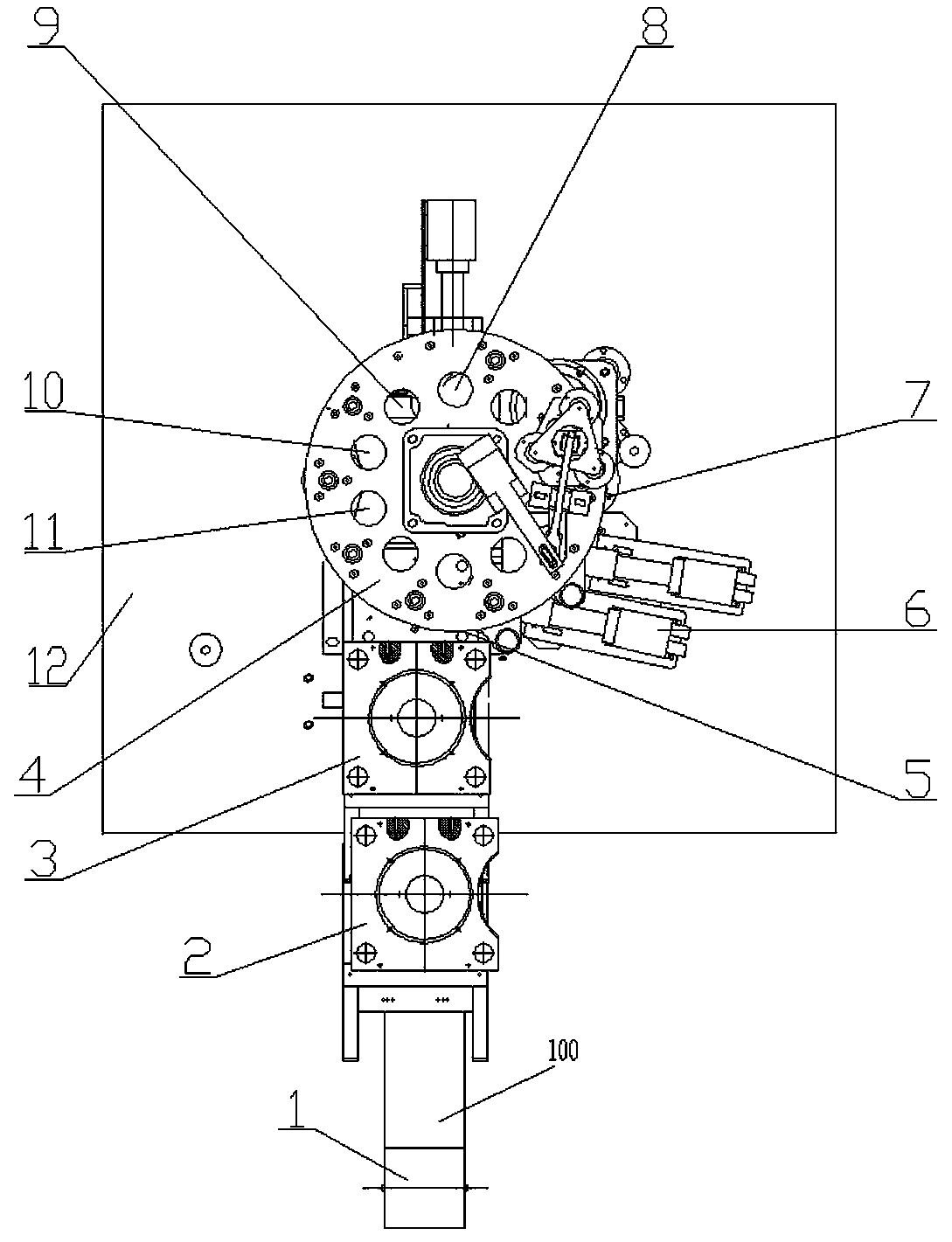
[0026] see figure 1 , a station arrangement structure of a paper cup lid forming machine, comprising a workbench 12, on which a master mold turntable 4 is rotatably arranged, and on the outside of the master mold turntable 4 along the path of the raw material paper 100 is sequentially arranged:

[0027] Unwinding station: used for raw paper 100 for unwinding and conveying;

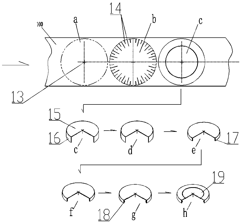
[0028] Punching cross seam station: used to punch out cross seams 13 on the raw paper...


PUM


Abstract

The invention discloses a paper cup cover forming machine station layout structure which comprises a workbench. A female die rotating disc is rotationally arranged on the workbench. An unreeling station, a cross stitch punching station and a first indentation station are sequentially arranged on the outer side of the female die rotating disc in the advancing path of raw material paper. A blankingforming station, a first heating forming station, a flanging station, a second heating station, a rolling station, a second indentation station and a cup cover discharging station are sequentially arranged below the female die rotating disc around the rotating center of the female die rotating disc according to the paper cup cover forming process steps. The blanking forming station is connected with the first indentation station, roll paper is directly adopted as raw materials of paper cup covers and is fed according to the takt during production, the structure has the advantages of being stable in performance, high in production efficiency and low in labor cost, and the produced paper cup covers are provided with fastening rings, and are tightly combined with opening edges of cups, and have good anti-disengagement anti-scattering anti-leaking effects.

Description

technical field [0001] The invention relates to the technical field of paper cup manufacturing machinery, in particular to a station arrangement structure of a paper cup lid forming machine. Background technique [0002] As a recyclable and degradable environmentally friendly product, paper cups are widely used to hold hot or cold drinks, such as coffee, milk and other liquid materials. Usually, in order to keep the materials clean and hygienic, they must be covered when using them. In the prior art, the cup lid is relatively loose. After covering the paper cup, the cup lid is easy to fall off, which can easily cause the drink in the cup to spill out; at the same time, the cup lid does not seal the paper cup tightly, and it is easy to cause the drink in the cup to leak when it is shaken. Extravasation, polluting the outside, affecting use; the existing manufacturing process of paper cup lids, such as the patent application number 201610848608.9, discloses a paper cup lid and...

Claims


Application Information

Patent Timeline
IPC IPC(8): B31D1/00
CPCB31D1/0018
Inventor 章明国
Owner RUIAN MINGGUO MACHINERY CO LTD
Learn More