Constant-ratio timing circuit for trailing edge timing

A constant-ratio timing and circuit technology, which is applied in the direction of electrical components, pulse processing, and delayed output pulse operation, can solve the problems of complex structure of constant-ratio timing circuits and affect circuit reliability, and achieve the effect of simple structure and improved stability

Active Publication Date: 2019-11-22
UNIV OF ELECTRONICS SCI & TECH OF CHINA
View PDF8 Cites 1 Cited by
  • Summary
  • Abstract
  • Description
  • Claims
  • Application Information

AI Technical Summary

Problems solved by technology

[0005] Aiming at the above-mentioned traditional constant-ratio timing circuit using two circuits for delay and attenuation, the structure is complex, and the reliability of the circuit is affected by the use of resistor divider to attenuate the DC component, the present invention proposes a trailing edge timing constant-ratio timing circuit The timing circuit uses an RC network to attenuate and delay at the same time, the structure is simple, and only the pulse signal is attenuated without affecting the DC component, which improves the reliability of the circuit

Method used


Image

  • Constant-ratio timing circuit for trailing edge timing
  • Constant-ratio timing circuit for trailing edge timing
  • Constant-ratio timing circuit for trailing edge timing

Examples


Embodiment Construction

[0013] The specific embodiments of the present invention will be described below with reference to the accompanying drawings.

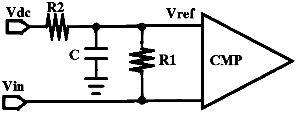
[0014] like figure 2 Shown is a schematic structural diagram of a constant-ratio timing circuit with trailing edge timing proposed by the present invention, including a first resistor R1, a second resistor R2, a capacitor C and a comparator CMP, and one end of the second resistor R2 is connected to the DC power supply Vdc, The other end is connected to one end of the first resistor R1 and the first input end of the comparator CMP and is grounded after passing through the capacitor C; the second input end of the comparator CMP is connected to the other end of the first resistor R1 and used as the input of the constant ratio timing circuit The terminal is connected to the input signal Vin, the output terminal is used as the output terminal of the constant ratio timing circuit, and the DC power supply Vdc is the same as the DC component of the input sig...


PUM


Abstract

The invention provides a constant-ratio timing circuit for trailing edge timing. The circuit comprises a first resistor, a second resistor, a capacitor and a comparator. One end of the second resistoris connected with a direct-current power supply, and the other end of the second resistor is connected with one end of the first resistor and the first input end of the comparator and then grounded through the capacitor. A second input end of the comparator is connected with the other end of the first resistor and an input signal of the constant-ratio timing circuit. An output end of the comparator serves as an output end of the constant-ratio timing circuit. The direct-current power supply and the input signal have the same direct-current component. According to the invention, only the pulsesignal is attenuated, and the direct current component remains unchanged, so that the stability of the circuit is improved compared with the attenuation of the direct current component and the pulsesignal in the traditional constant-ratio timing circuit. In addition, the attenuation and the time delay are achieved only through one RC network. Compared with a traditional constant-ratio timing circuit in which quantity signals are divided into two paths to be attenuated and delayed respectively, the structure is simpler.

Description

technical field [0001] The invention belongs to the technical field of analog integrated circuits, in particular to a constant-ratio timing circuit with trailing edge timing. Background technique [0002] Constant ratio timing is a timing method with a constant trigger ratio. The constant ratio timing circuit is mainly used in the laser ranging radar chip. Its function is to detect the reflected optical pulse signal and record the generation time of the reflected pulse, so as to provide the system to calculate the laser transmission distance and achieve the effect of ranging. In order to ensure the accuracy of the distance measurement, it is necessary to ensure that the time point when the comparator triggers each pulse signal on the receiving surface is the same. [0003] In the traditional constant-ratio timing circuit, the constant-ratio point at the leading edge of the input analog signal is used for timing triggering to form a standard digital signal. The point at whi...

Claims


Application Information

Patent Timeline
IPC IPC(8): H03K5/00H03K5/1252
CPCH03K5/00H03K5/1252H03K2005/00156H03K2005/00293
Inventor 张有润杨锐路统霄甄少伟张波
Owner UNIV OF ELECTRONICS SCI & TECH OF CHINA
Why Eureka
Try Eureka