Voltage regulation circuit, and nonlinear dimming circuit and method for LED lighting
A voltage adjustment circuit, non-linear technology, applied in electric light sources, lighting devices, electroluminescent light sources, etc., can solve the problems of being susceptible to external noise interference, PWM frequency stroboscopic, external noise interference, etc. , Good anti-noise performance, the effect of overcoming noise interference
- Summary
- Abstract
- Description
- Claims
- Application Information
AI Technical Summary
Problems solved by technology
Method used
Image
Examples
Embodiment 1
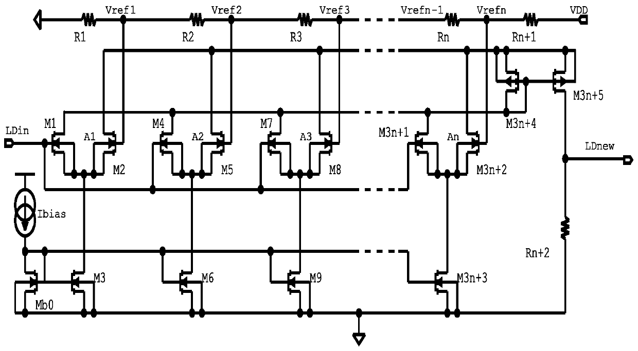
[0037] Please refer to figure 1 This embodiment provides a voltage adjustment circuit, which is configured to match and set the circuit gain according to the input voltage value, for non-linear adjustment of the input voltage to output;
[0038] The voltage adjustment circuit includes a summation current mirror circuit, a differential pair bias current mirror circuit, a reference voltage generation circuit, a current-to-voltage conversion circuit, and several mutually cascaded gain circuits;
[0039] In this embodiment, the gain circuit is a pair of NMOS transistors with a common source, the drain of the NMOS transistor is connected to the working voltage and the current input terminal of the summing current mirror circuit, and the gate is connected to the voltage input terminal and the reference voltage generating circuit respectively;
[0040] The reference voltage generating circuit is composed of voltage divider resistors matching the number of gain circuits in series, one end of ...
Embodiment 2
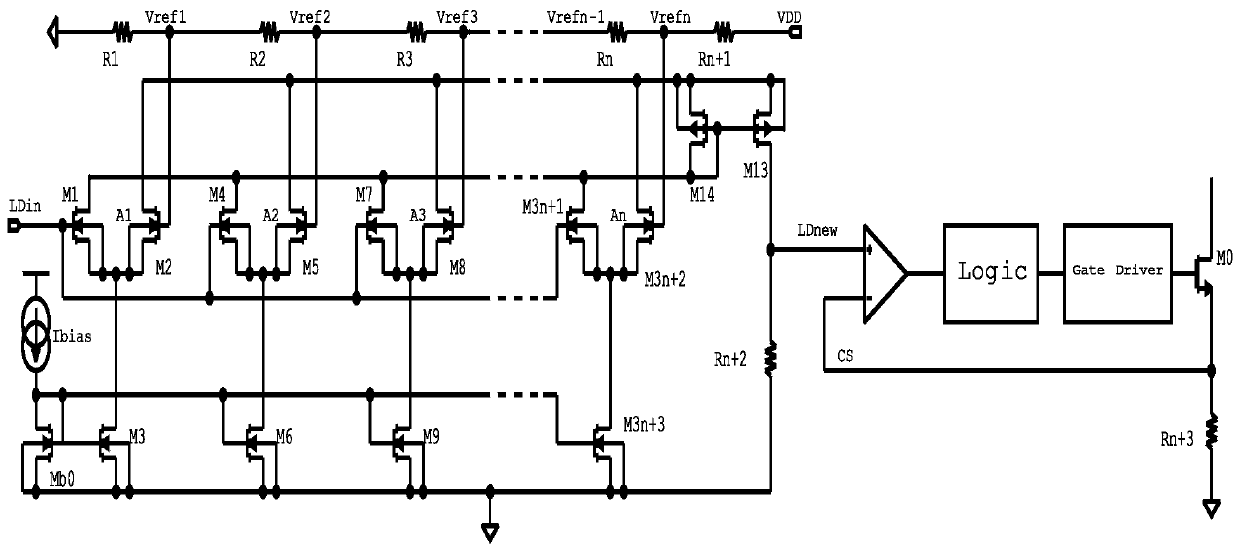
[0052] Please refer to figure 2 with image 3 On the basis of embodiment 1, this embodiment provides a non-linear dimming circuit for LED lighting, including a comparator circuit, a logic circuit, a gate drive circuit, a switch circuit and a current detection circuit that are cascaded in sequence, and such as In the voltage regulation circuit described in the first embodiment, the voltage output terminal of the voltage regulation circuit is connected to the non-inverting input terminal of the comparator circuit; the switch circuit in this embodiment uses a high-power MOS switch M0, and the current detection circuit current detection resistor Rn +2, and the inverting input terminal of the comparator circuit is connected to the common terminal of the MOS switch M0 and the detection resistor Rn+2.
[0053] Please refer to Figure 4 For the existing linear dimming circuit, the output signal is controlled through LD_Input to achieve the purpose of modulating the output LED current, th...
Embodiment 3
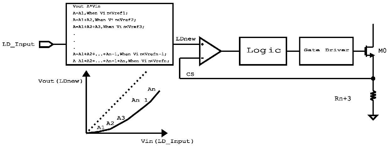
[0058] Please refer to image 3 On the basis of Embodiments 1 and 2, this embodiment provides a nonlinear dimming method for LED lighting, including:
[0059] Collect the value range of the input voltage value, and divide the value range according to the design requirements;
[0060] Determine the number of gain circuits according to the divided interval and set the gain size of each gain circuit;
[0061] According to the divided interval, determine the size of the reference voltage for triggering access of each gain circuit, and configure the reference voltage generation circuit;
[0062] Configure the summation current mirror circuit, the differential pair bias current mirror circuit, the current-voltage conversion circuit and the cascaded comparator circuit, logic circuit, and gate drive circuit in sequence;
[0063] Input voltage, perform voltage nonlinear adjustment, including:
[0064] If Vin1 , Then A=A1;
[0065] If Vref 1 ≤Vin2 , Then A=A1+A2;
[0066] If Vref 2 ≤Vin3 , Then A=A1...
PUM
 Abstract
Description
Claims
Application Information
 - R&D
- Intellectual Property
- Life Sciences
- Materials
- Tech Scout
- Unparalleled Data Quality
- Higher Quality Content
- 60% Fewer Hallucinations
Browse by: Latest US Patents, China's latest patents, Technical Efficacy Thesaurus, Application Domain, Technology Topic, Popular Technical Reports.
© 2025 PatSnap. All rights reserved.Legal|Privacy policy|Modern Slavery Act Transparency Statement|Sitemap|About US| Contact US: help@patsnap.com


