
High-precision eutectic welding equipment capable of maintaining constant pressing force

A eutectic welding, high-precision technology, applied in the direction of welding equipment, metal processing equipment, auxiliary devices, etc., can solve the problems that affect the welding quality, cannot guarantee the stability and badness of the two components to be welded, and achieve the improvement of eutectic welding Effect of precision and welding quality

Pending Publication Date: 2019-11-12
SUZHOU MAKING INTELLIGENT EQUIP CO LTD
View PDF1 Cites 4 Cited by
  • Summary
  • Abstract
  • Description
  • Claims
  • Application Information

AI Technical Summary

Problems solved by technology

[0003] During the soldering process, since the solder plating layer on the surface of the bottom sheet will change in volume as the temperature changes, from solid to liquid, during this process, a slight misalignment must occur between the two chips. If this dislocation is not corrected or avoided during the welding process, it will seriously affect the final welding quality and cause bad
[0004] During eutectic soldering, two chips need to be attached to each other. Since there are many circuit designs in the chip, the position accuracy requirements of the attachment are very high. In the prior art, such as CN201210179151.9 discloses an LED chip Eutectic welding equipment, which cannot guarantee the stability of the positions of the two components to be welded during the welding process

Method used


Image

  • High-precision eutectic welding equipment capable of maintaining constant pressing force
  • High-precision eutectic welding equipment capable of maintaining constant pressing force
  • High-precision eutectic welding equipment capable of maintaining constant pressing force

Examples


Embodiment

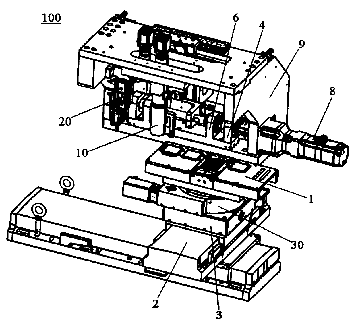
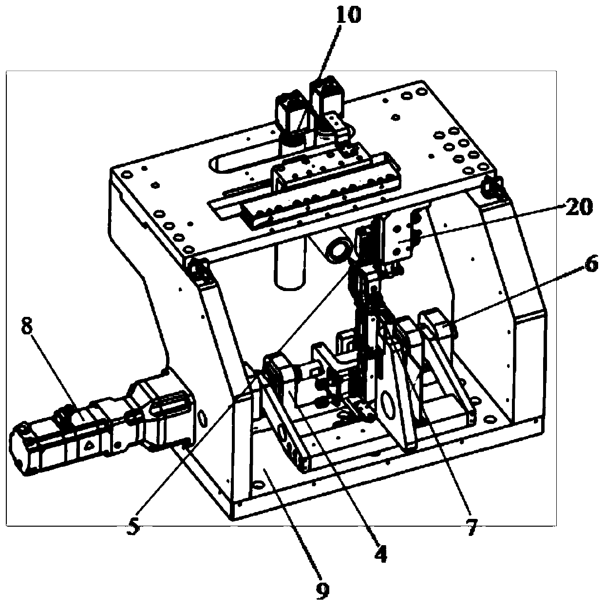
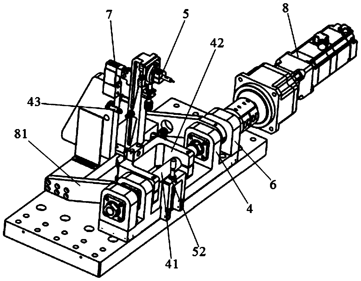
[0044] Please refer to Figure 1-Figure 12 , the present embodiment is a high-precision eutectic welding equipment 100 capable of maintaining a constant pressing force, which includes a eutectic soldering table 1 that supports and fixes a workpiece A, and an XY-axis drive unit that drives the eutectic soldering table 1 to move in a horizontal plane 2. Drive the eutectic soldering station 1 to fine-tune the Z-axis driving unit 3 on the Z-axis, the rotatable pressing head assembly 5 that is set on the first support 4 and presses the workpiece B, and the rotatable setting on the second The pressure sensor assembly 7 on the two bearings 6 and exerting pressure on the compression head assembly 5, and the servo driver 8 that drives the pressure sensor assembly 7 to rotate, the pressure sensor assembly 7 and the Z-axis drive unit 3 are in a closed loop control, when the pressure data of the pressure sensor assembly 7 is less than the set value, the Z-axis drive unit 3 drives the eute...


PUM

PropertyMeasurementUnit
melting pointaaaaaaaaaa

Abstract

The invention discloses high-precision eutectic welding equipment capable of maintaining constant pressing force. The equipment comprises a eutectic welding table which supports and fixes a workpieceA, an XY-axis driving unit driving the eutectic welding table to move in a horizontal plane, a Z-axis driving unit is driving the eutectic welding table to carry out fine adjustment on the Z axis, a pressing head assembly rotatably arranged on a first support and pressing a workpiece B, a pressure sensor assembly which is rotatably arranged on a second support and applies pressure to the pressinghead assembly, and a servo driving part which drives the pressure sensor assembly to rotate, the pressure sensor assembly is in closed-loop control with the Z-axis driving unit, and when pressure dataof the pressure sensor assembly is smaller than a set value, the Z-axis driving unit drives the eutectic welding table to move upwards until the data acquired by the pressure sensor assembly is in aset range. According to the equipment, the pressing force between eutectic welding core wire pieces can be effectively guaranteed to be constant, and the welding quality is improved.

Description

【Technical field】 [0001] The invention belongs to the technical field of eutectic welding, in particular to a high-precision eutectic welding equipment capable of maintaining a constant pressing force. 【Background technique】 [0002] Eutectic welding is also called low melting point alloy welding. Its basic characteristic is that two different metals can form alloys in a certain weight ratio at temperatures far below their respective melting points. The most common one is gold-silicon eutectic soldering. Gold has a melting point of 1063 degrees Celsius, while silicon has a melting point of 1414 degrees Celsius. If the silicon gold ratio of 2.85% and 97.15% is combined, a eutectic alloy body with a melting point of 363 degrees Celsius can be formed. This is the theoretical basis of gold-silicon eutectic welding. Gold-silicon eutectic soldering is usually used for soldering circuit boards. Many electronic components are sensitive to temperature, and with the gradual miniat...

Claims


Application Information

Patent Timeline
Patent Type & Authority Applications(China)
IPC IPC(8): B23K1/00B23K3/00B23K3/08B23K1/20
CPCB23K1/0008B23K3/00B23K3/08B23K3/085B23K1/20
Inventor 宋玉华葛宏涛李珂
Owner SUZHOU MAKING INTELLIGENT EQUIP CO LTD
Learn More