
A surface treatment device for powder metallurgy metal parts

A surface treatment device and powder metallurgy technology, applied in the field of metal processing, can solve the problems of not being able to smear on the surface of the gear, affecting the quality of the surface treatment, and the gear is prone to shaking, etc., to achieve comprehensive treatment, easy handling, and reduce the loss of lubricating oil.

Active Publication Date: 2021-06-08
赣州博立科技有限公司
View PDF0 Cites 0 Cited by
  • Summary
  • Abstract
  • Description
  • Claims
  • Application Information

AI Technical Summary

Problems solved by technology

[0006] The present invention can solve the problem that the existing equipment usually adopts the external clamping method to fix the gear when treating the surface of the gear, which is inconvenient to process the outer surface of the gear, and the gear is prone to shaking during the treatment process, which affects the subsequent surface treatment quality; and The existing equipment is affected by the gear structure during the surface treatment of the gear. The burrs in the gap between the gear teeth cannot be completely removed, the treatment effect is not good, and the treatment efficiency is low. After the surface treatment is completed, the gear surface cannot be smeared with lubricating oil in time for maintenance. And other issues

Method used


Image

  • A surface treatment device for powder metallurgy metal parts
  • A surface treatment device for powder metallurgy metal parts
  • A surface treatment device for powder metallurgy metal parts

Examples


Embodiment Construction

[0024] Embodiments of the present invention will be described below with reference to the drawings. In the process, in order to ensure the clarity and convenience of illustration, we may exaggerate the width of the lines or the size of the constituent elements in the diagram.

[0025] In addition, the following terms are defined based on the functions in the present invention, and may be different according to the user's or operator's intention or practice. Therefore, these terms are defined based on the entire content of this specification.

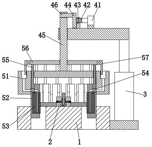
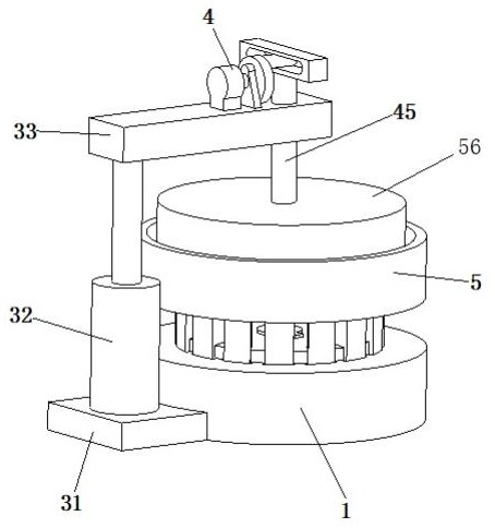
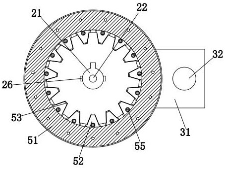
[0026] Such as Figure 1 to Figure 4 As shown, a surface treatment device for powder metallurgy metal parts includes a workbench 1, a limit unit 2, a support unit 3, a drive unit 4 and a processing unit 5; Hole, the upper middle part of the workbench 1 is equipped with a limit unit 2, the left outer wall of the workbench 1 is equipped with a support unit 3, the upper end of the support unit 3 is provided with a drive unit 4, and the lo...


PUM


Abstract

The invention provides a surface treatment device for powder metallurgy metal parts, comprising a workbench, a limit unit, a support unit, a drive unit and a processing unit; the workbench is uniformly provided with trapezoidal through holes along its circumferential direction, A limit unit is installed in the middle of the upper end, a support unit is installed on the left outer wall of the workbench, a drive unit is arranged at the upper end of the support unit, and a processing unit is connected to the lower end of the drive unit; The gear is fixed by the external clamping method, which is not convenient for processing the outer surface of the gear, and the gear is prone to shaking during the processing, which affects the quality of the subsequent surface treatment; and the existing equipment is affected by the gear structure when the surface of the gear is treated. , The burrs in the gap between the gear teeth cannot be completely removed, the treatment effect is not good, the treatment efficiency is low, and after the surface treatment is completed, the gear surface cannot be smeared with lubricating oil for maintenance.

Description

technical field [0001] The invention relates to the technical field of metal processing, in particular to a surface treatment device for powder metallurgy metal parts. Background technique [0002] Powder metallurgy is an industrial technology that uses metal powder as a raw material to make metal products through forming and sintering. Using powder metallurgy technology can directly make porous, semi-dense or full-dense products, such as bearings, gears, cams, etc. Since the surface of powder metallurgy products mainly has defects such as a large number of pores or some burrs and hard spots, the surface treatment of the products is required before use, especially when the surface of the gear is treated, the main problems are as follows: [0003] 1. Existing equipment often adopts external clamping method to fix the gear when treating the surface of the gear, which is not convenient for processing the outer surface of the gear, and the gear is prone to shake during the proc...

Claims


Application Information

Patent Timeline
Patent Type & Authority Patents(China)
IPC IPC(8): B22F3/24B22F5/08
CPCB22F3/24B22F5/08B22F2003/242
Inventor 闫晶晶胡才富
Owner 赣州博立科技有限公司
Learn More