
DC Fault Isolation Method Based on Isolated Modular DC Transformer

A DC transformer and DC fault technology, applied in the direction of DC power input conversion to DC power output, DC network circuit devices, instruments, etc., can solve the problems of fast development speed and high difficulty in fault isolation, and achieve fast fault isolation speed and fault clearance. The method is simple and the effect of speeding up the zero-crossing time

Active Publication Date: 2021-10-08
TIANJIN UNIV
View PDF0 Cites 0 Cited by
  • Summary
  • Abstract
  • Description
  • Claims
  • Application Information

AI Technical Summary

Problems solved by technology

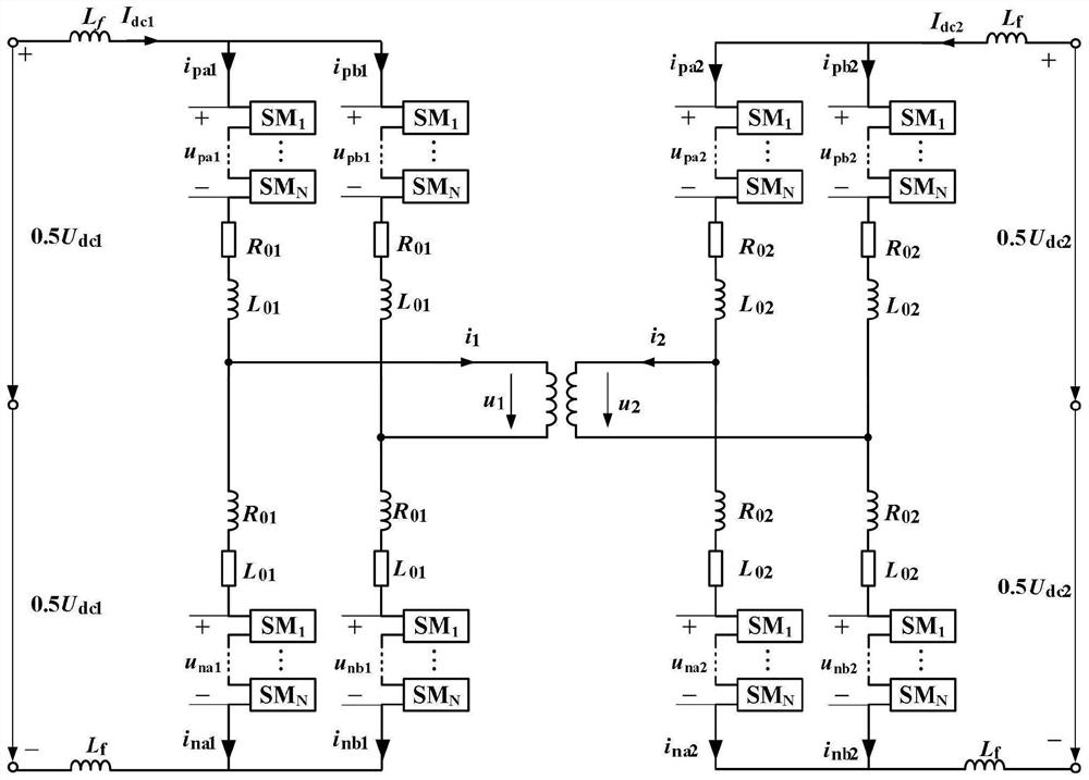
[0009] Aiming at the current fault development speed of DC distribution network is fast, fault isolation is difficult, and the traditional DC transformer-based DC distribution network fault isolation method is difficult to ensure the fault isolation speed and at the same time have better economical problems, the present invention provides An isolated modular multilevel DC-DC transformer with DC fault self-clearing capability based on the improved half-bridge sub-module, and a corresponding fault isolation strategy is designed to achieve fast DC fault clearing

Method used


Image

  • DC Fault Isolation Method Based on Isolated Modular DC Transformer
  • DC Fault Isolation Method Based on Isolated Modular DC Transformer
  • DC Fault Isolation Method Based on Isolated Modular DC Transformer

Examples


Embodiment Construction

[0027] The present invention will be described more fully below with reference to the accompanying drawings.

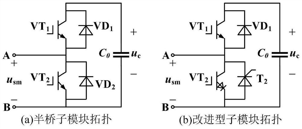
[0028] figure 1 (a) shows the half-bridge sub-module (HBSM) structure. The low component count of the half-bridge sub-module results in low operating losses. However, in order to ensure the safety of the IGBT, a diode must be connected in parallel to prevent the IGBT from being subjected to reverse voltage. When a fault occurs on the DC side, due to the parallel diode ( figure 1 Due to the freewheeling effect of VD2) in (a), the HBSM-based modular transformer cannot complete fault self-clearing, and cannot block the feed current on the AC side.

[0029] figure 1 (b) shows the improved half-bridge sub-module structure adopted by the present invention. Thyristors are used to replace the freewheeling diodes in the half-bridge sub-module, and reverse-resistance IGBTs are used to replace the IGBTs in the parallel branch. In the normal working state, the conduction si...


PUM


Abstract

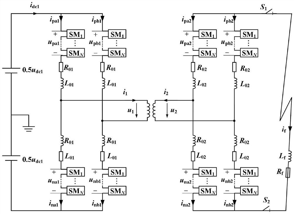
The invention relates to a DC fault isolation method based on an isolated modular DC transformer. The adopted isolated modular DC transformer is based on an improved half-bridge sub-module: a set of anti-parallel structures composed of IGBT VT1 and diode VD1 and a sub-module The module capacitor C is connected in series and connected in parallel with the anti-parallel structure composed of reverse resistance IGBT VT2 and thyristor T2. The emitter of VT1 is connected to the collector of VT2, and the collector and emitter of VT2 are respectively connected to the input and output of the sub-module. , Reverse resistance IGBT VT2 adopts IGBT with reverse resistance function, namely RB-IGBT, or adopts IGBT and diode in series in the same direction; when a fault occurs in the DC line, once a fault is detected, it will be turned off by sending a shutdown command to the sub-module. All IGBTs, and cancel the turn-on signal of the thyristor, and at the same time change the voltage modulation mode of the inverter on the sound side, so that the bridge arm current in the inverter on the fault side crosses zero in turn to realize the shutdown of the bridge arm, and complete the fault clearance and isolation. .

Description

technical field [0001] The invention relates to the field of power electronics and power systems. Aiming at the difficulty in achieving the balance between fault isolation speed and system economy in the existing flexible DC system fault isolation method, the DC fault self-clearing capability is adopted under full consideration of equipment investment and loss. An isolated modular multilevel DC-DC transformer based on the improved half-bridge sub-module, and a DC fault isolation method is given. Background technique [0002] With the gradual depletion of traditional fossil energy, the world's environmental problems have become increasingly prominent, and countries have turned their attention to green and clean energy. Accelerating the transformation of energy types, adjusting the energy structure, and promoting the use of renewable energy have become the general trend. In the transmission and distribution of renewable energy, the DC transmission and distribution system has ...

Claims


Application Information

Patent Timeline
Patent Type & Authority Patents(China)
IPC IPC(8): H02H7/12H02M3/335H02J1/00H02J3/36
CPCH02H7/1213H02J1/00H02J3/36H02M3/33523H02M3/33576Y02E60/60
Inventor 李斌刘海金温伟杰吕慧
Owner TIANJIN UNIV
Learn More