Automatic detecting and positioning device and method of laser spot focus

An automatic detection and laser spot technology, which is applied to measurement devices, optical devices, instruments, etc., can solve the problems of inability to respond to the deep ultraviolet band laser, the influence of laser transmission absorption and attenuation, and the inability to detect the size of the focal point at the same time. The effect of flexibility, relatively low construction cost and low construction cost

Pending Publication Date: 2019-11-05
NAT UNIV OF DEFENSE TECH
View PDF2 Cites 13 Cited by
  • Summary
  • Abstract
  • Description
  • Claims
  • Application Information

AI Technical Summary

Problems solved by technology

[0004] In the prior art, as disclosed in Japanese Patent Document No. 6-7980 and Chinese Patent Document CN 102974936, the determination of the position of the focal point depends on the detection of the plasma light by the photoelectric sensor, but the specific size of the focal point cannot be detected at the same time.
[0005] In the deep ultraviolet electromagnetic wave band, laser transmission is greatly affected by water vapor absorption and attenuation, and the adjustment and construction of the optical path must be carried out under vacuum conditions, so plasma light cannot be generated due to gas ionization. In addition, conventional CCD cameras basically cannot respond to deep ultraviolet band laser, only photodetectors made of gallium nitride (GaN) or aluminum gallium nitride (AlGaN) materials in the market can respond well to electromagnetic waves in the 100 to 300nm band

Method used


Image

  • Automatic detecting and positioning device and method of laser spot focus
  • Automatic detecting and positioning device and method of laser spot focus
  • Automatic detecting and positioning device and method of laser spot focus

Examples


Embodiment 1

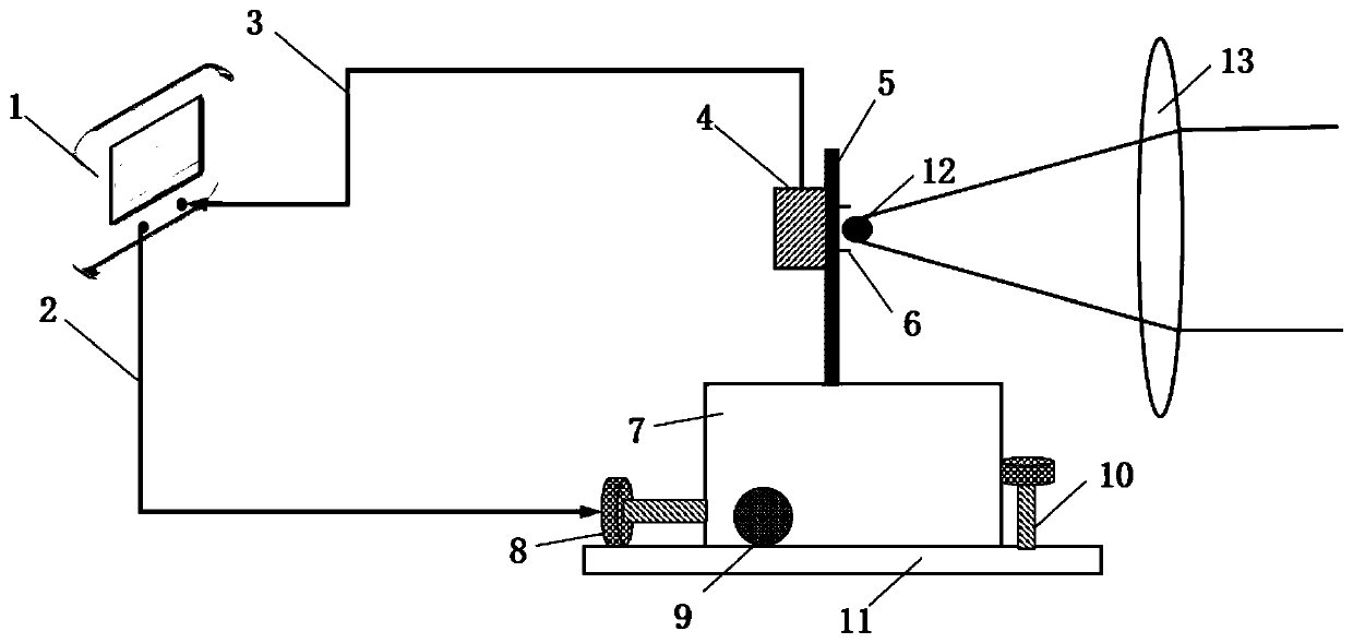
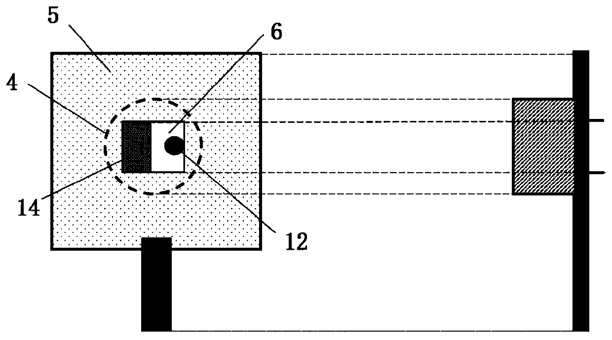
[0038] An automatic detection and positioning device for laser spot focus, which includes a central processing unit 1, a signal sending line 2, a signal receiving line 3, a photodetector 4, a spot detection surface 5, a stage 7, and a Z-direction stepping motor 8 , X to the stepping motor 9, Y to the stepping motor 10, focusing lens 13; The central processing unit 1 is connected with the photodetector 4 through the signal receiving line 3, and is used to receive the current signal sent by the photodetector 4; The photodetector 4 is used to detect the laser light signal, and convert the light signal linearly into a current intensity signal; the central processing unit 1 communicates with the Z-direction stepping motor 8 and the X-direction stepping motor 9 respectively through the signal transmission line 2 , Y is connected to the stepper motor 10, and is used to send movement control commands to the Z-direction stepper motor 8, X-direction stepper motor 9 and Y-direction steppe...

Embodiment 2

[0044] A method for automatic positioning of laser beam focus and sample positioning, characterized in that it uses the automatic detection and positioning device of laser spot focus of embodiment 1, comprising the following steps:

[0045] S1. Put the focused spot from the laser light source and focused by the focusing lens 13 on the spot detection surface 5, and try to position it on the edge of the incident hole of the spot;

[0046] S2. The central processing unit 1 sends a single-step movement instruction to the X-direction stepping motor 9 or Y-direction stepping motor 10, and the X-direction stepping motor 9 or Y-direction stepping motor 10 moves in place according to the instruction, and the central processing unit 1 receives to the current signal sent by the photodetector 4; the central processing unit 1 records the position coordinates and the current signal strength of the X direction stepper motor 9 or Y direction stepper motor 10 at this moment; repeat the above-me...


PUM


Abstract

The invention provides an automatic detecting and positioning device of a laser spot focus. A photoelectric detector (4) of the device detects a laser spot focused by a focusing lens (13) from a spotincidence hole of a spot detecting face (5) to obtain signals, the signals are sent by a signal sending line (3) to a central processing unit (1) connected with the signal sending line, and the central processing unit (1) sends a movement instruction to an X-directional, Y-directional and Z-directional stepping motor connected with the central processing unit (1) through a signal receiving line (3) according to spot signal data changes until the spot detecting face (5) moves to the laser focus. By means of the automatic detecting and positioning device, feedback adjustment is conducted on theposition of the spot detecting face through a horizontal movement table control module, the automatic search of the position of the laser focus is realized, the precise setting of a to-be-detected sample can be realized, and the scanning and imaging of a tiny spot can be realized through a filtering image reconstruction module. The automatic detecting and positioning device is suitable for a supervacuum closed space and has the remarkable advantages of being easy to operate, flexible in measurement method, simple in system framework, low in construction cost and the like.

Description

technical field [0001] The invention generally belongs to the technical field of high-ultra-vacuum laser diagnosis and characterization, and in particular relates to an automatic positioning and detection device for laser spot focus, and provides a method for moving a sample to the focus point. Background technique [0002] Laser is the light generated by the stimulated radiation of atoms, and the excited photon beam has highly consistent optical properties. This makes the laser have the advantages of good monochromaticity, high brightness and good directionality compared with ordinary light sources. Lasers are widely used, such as laser marking, laser welding, laser cutting, etc. In actual application, the laser focal length of the focusing system will be slightly different due to different focusing lenses and optical systems. How to quickly and accurately obtain the laser focal length of the focusing system has become a difficult problem in the laser application process....

Claims


Application Information

Patent Timeline
Patent Type & Authority Applications(China)
IPC IPC(8): G01B11/00G01B11/03G01B11/06
CPCG01B11/002G01B11/03G01B11/0608
Inventor 张超凡毛元昊闫申郭川杨子宁王红岩韩凯许晓军
Owner NAT UNIV OF DEFENSE TECH
Why Eureka
Try Eureka