
Cutter pose optimization method

An optimization method, tool technology, applied in the field of machinery to improve surface properties, avoid interference and chatter

Active Publication Date: 2019-11-05
CHONGQING UNIV
View PDF5 Cites 3 Cited by
  • Summary
  • Abstract
  • Description
  • Claims
  • Application Information

AI Technical Summary

Problems solved by technology

Unfortunately, the existing literature on tool pose optimization does not consider all three aspects simultaneously

Method used


Image

  • Cutter pose optimization method
  • Cutter pose optimization method
  • Cutter pose optimization method

Examples


Embodiment Construction

[0060] Hereinafter, preferred embodiments of the present invention will be described in detail with reference to the accompanying drawings. It should be understood that the preferred embodiments are only for illustrating the present invention, but not for limiting the protection scope of the present invention.

[0061] Glossary:

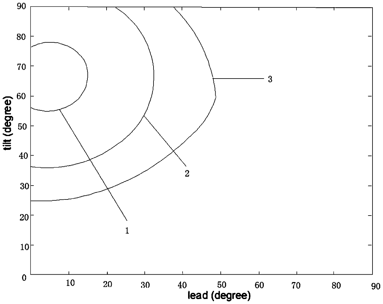
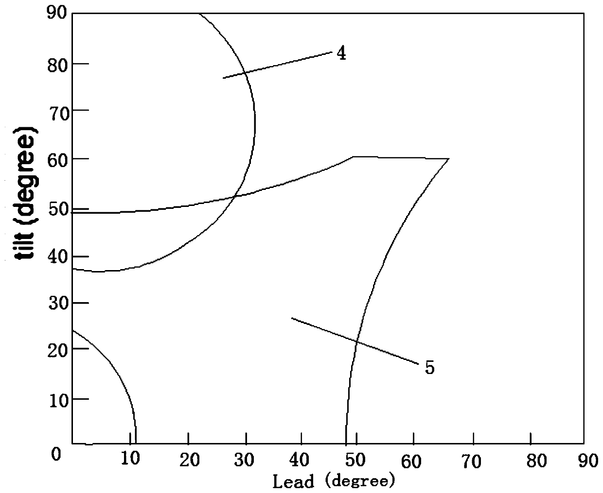
[0062] Tool attitude: Given a tool contact point, expressed by the tool’s lead angle α and inclination β, that is, (α i , β i ) indicates that the lead angle is: the angle between the tool axis projected onto the XOZ plane of the feed coordinate system and the Z axis of the feed coordinate system. The inclination angle is: the angle between the tool axis projected onto the YOZ plane of the feed coordinate system and the Z axis of the feed coordinate system. Since the tool attitude with a negative angle is usually not used in actual machining, the ranges of lead angle α and inclination β in this method are both (0°, 90°).

[0063] Feed coordinate ...


PUM


Abstract

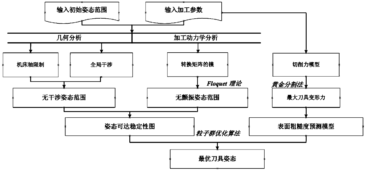
The invention discloses a cutter pose optimization method specifically comprising the steps that S1, the accessibility range of a cutter under the limit of a machine tool shaft is determined; S2, global-interference-free pose range of the cutter is obtained; S3, the flutter-free pose range of the cutter is obtained; S4, a cutter pose accessibility stability diagram is built; and S5, on the basis of S4, the optimal cutter pose is obtained with a surface roughness prediction model as a fitness function. According to the cutter pose optimization method, the surface roughness prediction model of aworkpiece serves as the fitness function, the optimal cutter pose is obtained, interference and flutter in the machining process are avoided, surface performance of the workpiece is also improved, and significance is achieved for route planning.

Description

technical field [0001] The present invention relates to the mechanical field, and in particular, relates to a tool posture optimization method. Background technique [0002] Five-axis machining has the advantages of less installation times, flexible machining paths, and high machining efficiency, and has been widely used in industries such as automotive, aerospace, and shipbuilding. The tool attitude selection in path planning is the key to make full use of these advantages. Many literatures have studied the problem of tool attitude optimization in five-axis machining. In these literatures, research on tool attitude optimization can be divided into two categories. [0003] The first and most studied category is the avoidance of interference, which can lead to workpiece and tool damage. Choi et al. proposed an algorithm to convert the data of tool contact points into tool position data, and then use surface properties to detect interference from the tool position data. Ch...

Claims


Application Information

Patent Timeline
IPC IPC(8): B23Q15/00
CPCB23Q15/00
Inventor 王四宝王时龙易力力康玲杨波马驰赵增亚王泽华
Owner CHONGQING UNIV
Learn More