


Quick Research
Generate reliable direction feasibility study reports for your R&D in just a few steps.

Technical Q&A
Discover and master advanced knowledge NOW. Basics, ideas, possibilities, all at once.

Find Solutions
As an expert in R&D theories, this can generate solutions to your technical problems instantly.

Evaluate Feasibility
Analyze your overall solution with one click, know your potential R&D risks in advance.

Monitor Landscape
Get weekly tech updates, stay abreast of the latest tech innovations and key insights.
Molded body for joining and method for manufacturing same
A technology of moldings and mixtures, which is used in semiconductor/solid-state device manufacturing, manufacturing tools, welding equipment, etc., and can solve the problem of difficult and high-strength semiconductor chip components being bonded to substrates.
- Summary
- Abstract
- Description
- Claims
- Application Information
AI Technical Summary
Problems solved by technology
Method used
Image


Examples
Embodiment 1
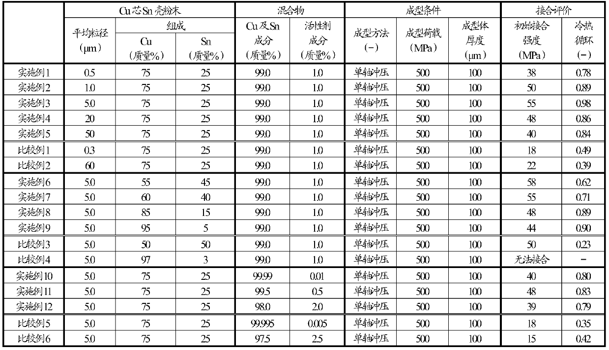
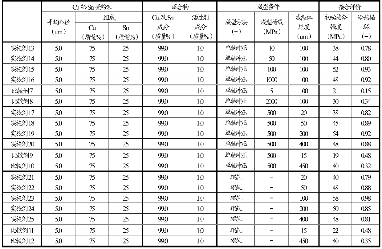
[0034] A Cu core Sn shell powder having an average particle diameter of 0.5 μm, a Cu ratio of 75% by mass, and a Sn ratio of 25% by mass was prepared. Here, the composition ratio of Cu and Sn of the Cu core Sn shell powder is measured by ICP emission spectrometry (manufactured by Thermo Fisher Scientific, iCAP-6500 Duo). In addition, the crystal structure of the core-shell structure was mainly composed of Cu and Sn, and it was confirmed by a powder X-ray diffraction method (manufactured by PANalytical, a multipurpose X-ray diffractometer Empyrean). Next, under a nitrogen atmosphere, the Cu core Sn shell powder was put into a mortar, and a general-purpose flux (92MS manufactured by Arakawa Chemical Industries, Ltd.) was added to the Cu core Sn shell powder and mixed uniformly for 30 minutes to obtain a mixture. In this mixture, the gaps between the Cu core Sn shell powder, that is, the inner walls of the closed pores and the open pores are covered with the active agent content. ...
Embodiment 2~5 and comparative example 1、2
[0036] In Examples 2 to 5 and Comparative Examples 1 and 2, as shown in Table 1, regarding the average particle size of the Cu core Sn shell powder used to make the bonding molded body, the average particle size of the Cu core Sn shell powder that is different from that of Example 1 was used. Cu core Sn shell powder, in the same manner as in Example 1, a molded body for joining was obtained.
Embodiment 6~9 and comparative example 3、4
[0038] In Examples 6 to 9 and Comparative Examples 3 and 4, as shown in Table 1, the Cu and Sn compositions of the Cu core Sn shell powder used to make the bonding molded body were Cu and Sn different from those in Example 1. The Cu core Sn shell powder having the composition of Sn was used in the same manner as in Example 1 to obtain a bonding molded body.
PUM
| Property | Measurement | Unit |
|---|---|---|
| thickness | aaaaa | aaaaa |
| particle diameter | aaaaa | aaaaa |
| particle size | aaaaa | aaaaa |
Abstract
Description
Claims
Application Information
 - R&D Engineer
- R&D Manager
- IP Professional
- Industry Leading Data Capabilities
- Powerful AI technology
- Patent DNA Extraction
Browse by: Latest US Patents, China's latest patents, Technical Efficacy Thesaurus, Application Domain, Technology Topic, Popular Technical Reports.
© 2024 PatSnap. All rights reserved.Legal|Privacy policy|Modern Slavery Act Transparency Statement|Sitemap|About US| Contact US: help@patsnap.com