Sludge and wastewater recovery device for belt conveyor cleaning

A waste water recycling, belt conveyor technology, applied in the direction of cleaning devices, transportation and packaging, conveyor objects, etc., can solve the problems of wasting water resources and conveying materials, and cannot be cleaned up, so as to reduce infrastructure construction and reduce secondary pollution. , the effect of optimizing the production process

Pending Publication Date: 2019-11-01
JIAOZUO CREATION HEAVY IND CO LTD
View PDF0 Cites 0 Cited by
  • Summary
  • Abstract
  • Description
  • Claims
  • Application Information

AI Technical Summary

Problems solved by technology

[0002] Belt conveyors (such as image 3 21 in ) When transporting materials, conventional mechanical cleaners often cannot clean them up, and need to use cleaning water tanks (such as image 3 Shown in 22) in the high-pressure water to clean it, the cleaned sludge and waste water through the pipeline (such as image 3 shown in 23) into the sedimentation tank (such as image 3 24 in ), the sediment needs to be manually cleaned up again, and the overflowing sewage cannot be returned to the cleaning water tank (such as image 3 22 in ), the disadvantages of secondary utilization are: (1) infrastructure such as sedimentation tanks is required; (2) manual secondary cleaning is required; (3) there is a hidden danger of secondary pollution; (4) waste Water resources and transport materials

Method used


Image

  • Sludge and wastewater recovery device for belt conveyor cleaning
  • Sludge and wastewater recovery device for belt conveyor cleaning
  • Sludge and wastewater recovery device for belt conveyor cleaning

Examples


Embodiment Construction

[0020] The present invention will be clearly described below in conjunction with the drawings and specific embodiments in the embodiments of the present invention. The description here is only used to explain the present invention, but not as a limitation to the present invention. Based on the embodiments of the present invention, all other embodiments obtained by those skilled in the art without creative work, any modifications, equivalent replacements, improvements, etc., shall be included in the protection scope of the present invention Inside.

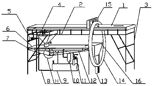
[0021] Such as Figure 1-2 As shown, the present invention provides a sludge and waste water recovery device for belt conveyor cleaning, including a belt conveyor, the belt conveyor includes a conveyor belt 1, a truss 2 and a support 3, and the conveyor belt 1 is arranged on the truss 2, The truss 2 is supported on the bracket 3, and the sludge and waste water recovery device for belt conveyor cleaning also includes a hydraulic cl...


PUM


Abstract

The invention discloses a sludge and wastewater recovery device for belt conveyor cleaning. The device comprises a belt conveyor, a hydraulic sweeping box, a solid-liquid separation device and a pipechain machine, wherein a conveying belt is arranged on a truss, the truss is arranged on and supported by supports, the hydraulic sweeping box is connected to the truss, a scraper and a spray pipe arearranged in the hydraulic sweeping box, a slurry pipe is arranged at the lower end of the hydraulic sweeping box, a cutting-off valve is arranged on the slurry pipe, the solid-liquid separation device is arranged at the bottom of the slurry pipe, a solid discharging port of the solid-liquid separation device is connected with a feeding hopper of the pipe chain machine, the pipe chain machine is connected to the truss through a pipe chain machine support, a support column is arranged at the bottom of the pipe chain machine, a material discharging pipe of the pipe chain machine is arranged above a conveying belt feeding section, a liquid discharging pipe of the solid-liquid separation device is connected with a circulating pump, and the circulating pump is connected with the spray pipe. Thedevice has the beneficial effects that the production process is optimized, the infrastructure construction can be reduced, the investment and operation cost can be reduced, the secondary pollution can be reduced, and materials and water resources can be recycled to the maximum.

Description

technical field [0001] The invention relates to the technical field of belt conveyor cleaning, in particular to a sludge and waste water recycling device used for belt conveyor cleaning. Background technique [0002] Belt conveyors (such as image 3 21 in ) When transporting materials, conventional mechanical cleaners often cannot clean them up, and need to use cleaning water tanks (such as image 3 Shown in 22) in the high-pressure water to clean it, the cleaned sludge and waste water through the pipeline (such as image 3 shown in 23) into the sedimentation tank (such as image 3 24 in ), the sediment needs to be manually cleaned up again, and the overflowing sewage cannot be returned to the cleaning water tank (such as image 3 22 in ), the disadvantages of secondary utilization are: (1) infrastructure such as sedimentation tanks is required; (2) manual secondary cleaning is required; (3) there is a hidden danger of secondary pollution; (4) waste water resources and transp...

Claims


Application Information

Patent Timeline
Patent Type & Authority Applications(China)
IPC IPC(8): B65G45/22B65G45/26
CPCB65G45/22B65G45/26
Inventor 杨家立苗要当马科田爽张恩照黄小路
Owner JIAOZUO CREATION HEAVY IND CO LTD
Why Eureka
Try Eureka