Set of cutting inserts and methods of making a set of cutting inserts

A technology of cutting inserts and cutting edges, applied in the manufacture of tools, additive manufacturing, accessories of tool holders, etc., can solve the problems of difficult handling and fixing, difficulty in pressing thin inserts, difficulty in grooving or cutting inserts, etc., to reduce losses. Effect

Active Publication Date: 2019-10-29
SECO TOOLS AB
View PDF9 Cites 0 Cited by
  • Summary
  • Abstract
  • Description
  • Claims
  • Application Information

AI Technical Summary

Problems solved by technology

Manufacturing any type of blade via this pressing technique, especially small grooving or parting off blades can be particularly difficult
First, pressing thin blades can be difficult
Furthermore, handling and securing them throughout the production process can be difficult

Method used


Image

  • Set of cutting inserts and methods of making a set of cutting inserts
  • Set of cutting inserts and methods of making a set of cutting inserts
  • Set of cutting inserts and methods of making a set of cutting inserts

Examples


Embodiment Construction

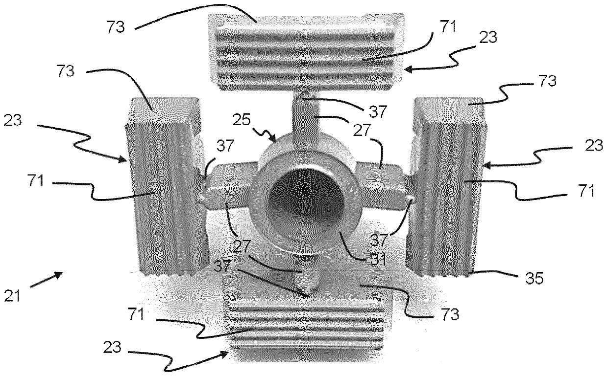
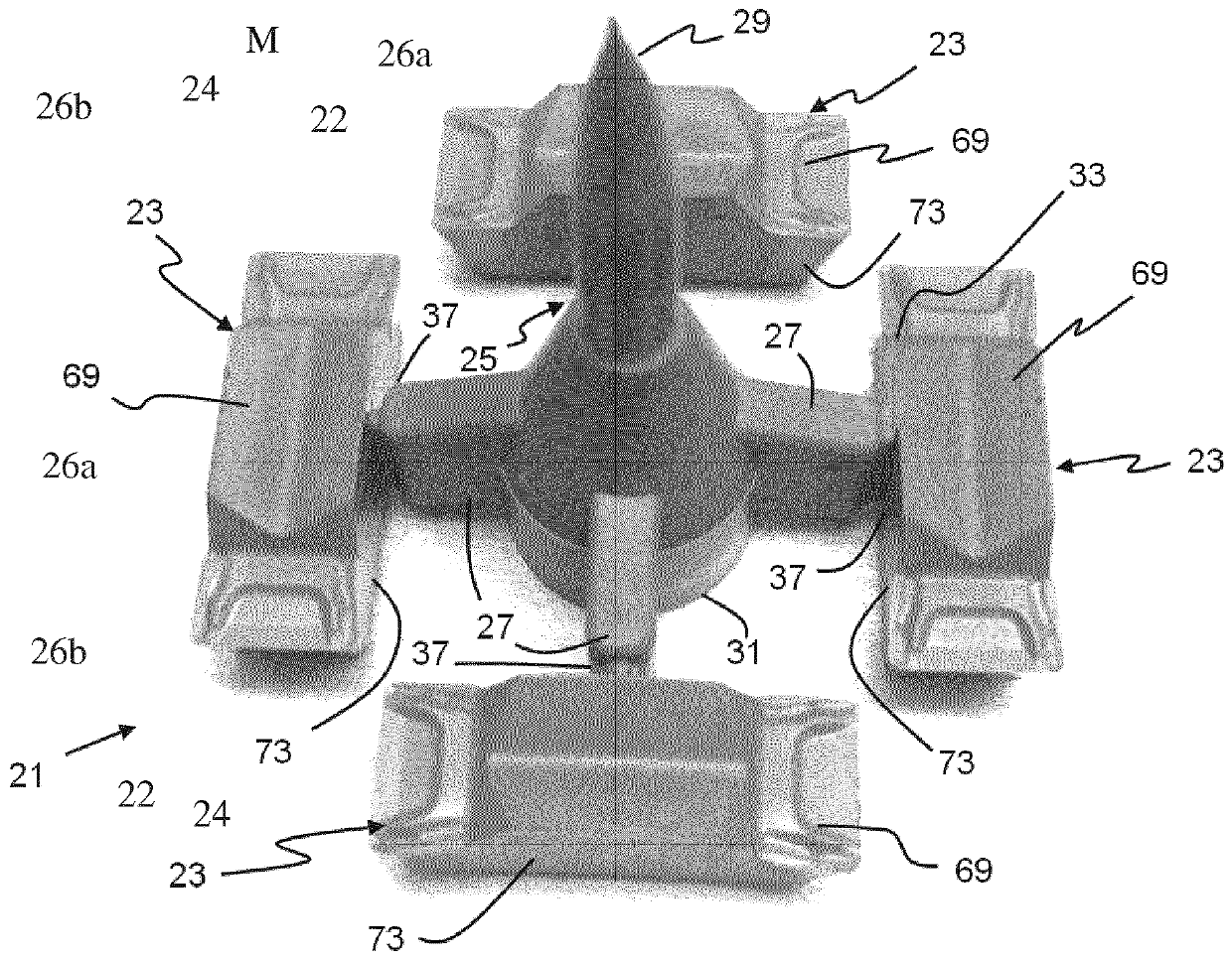
[0034] According to one aspect of the invention a set 21 of cutting inserts 23 in Figure 1A and 1B shown in , and which includes a runner portion, a support structure or stem portion 25, a plurality of runner portions or branch portions 27 attached to and extending from the stem portion, and a plurality of branch portions attached to the stem portion At least one cutting blade 23 for each branch portion. The stem portion 25 has a longitudinal axis extending between a top end 29 and a bottom end 31 of the stem portion, and at least one of the top end and the bottom end of the stem portion is arranged above and above a respective uppermost portion 33 of each cutting blade 23, respectively. Below the lowermost part 35 . In other words, there is at least one of: (A) the top end 29 of the stem portion 25 is arranged above the uppermost portion 33 of each cutting insert 23 along the longitudinal axis and (B) the bottom end 31 of the stem portion along the The longitudinal axis is...


PUM


Abstract

A set (21, 21a, 21b, 21c, 121, 221, 321, 421) of cutting inserts (23, 23a, 23b, 23c, 123, 223, 323, 423) includes a stem portion (25, 25a, 25b, 25c, 125, 225, 325, 425), a plurality of branch portions(27, 27a, 27b, 27c, 127, 227, 327, 427) attached to and extending from the stem portion (25, 25a, 25b, 25c, 125, 225, 325, 425), and at least one cutting insert (23, 23a, 23b, 23c, 123, 223, 323, 423) attached to each of the plurality of branch portions (27, 27a, 27b, 27c, 127, 227, 327, 427). Preferably, the stem portion (25, 25a, 25b, 25c, 125, 225, 325, 425) has a longitudinal axis extending between a top end (29, 29a, 29b, 29c, 129) of the stem portion and a bottom end (31, 31a, 31b, 31c, 131) of the stem portion and at least one of the top end of the stem portion (25, 25a, 25b, 25c, 125,225, 325, 425) is disposed along the longitudinal axis above uppermost portions (33, 33a, 33b, 33c) of each cutting insert, and the bottom end (35, 35a, 35b, 35c) of the stem portion is disposed along the longitudinal axis below lowermost portions of each cutting insert. Also, methods for manufacturing a set of cutting inserts are disclosed.

Description

technical field [0001] The present invention relates to cutting inserts, and more particularly to cutting insert sets and methods of manufacturing cutting insert sets. The invention also relates to a mold for forming a cutting insert set and a method of machining a groove using the cutting insert. Background technique [0002] Replaceable cutting inserts for cutting tools are typically manufactured one at a time via a manufacturing process that involves pressing carbide powder in a mold to form a green insert, sintering the green insert, and then, if desired, Perform additional grinding or finishing processes. [0003] Inserts with complex shapes are expensive to produce (either with conventional pressing or by utilizing Multi-Axis Press (MAP) and / or Powder Injection Molding (PIM) techniques) and they are often subjected to costly operations such as grinding and fixing one after the other . Manufacturing any type of blade, especially small grooving or parting off blades, ...

Claims


Application Information

Patent Timeline
IPC IPC(8): B23C5/22B23B27/14B23P15/28B29C45/00
CPCB23C5/2213B23B27/14B22F2005/001B23B2270/16B22F3/225B22F5/003C22C29/08B33Y10/00B33Y80/00B23P15/28Y02P10/25B22F10/66B22F10/64B22F10/28B23B27/145B23B2222/28B28B1/001B28B1/24B23C5/202
Inventor 马茨·强森佩尔·强森米卡埃尔·格伦奎斯特玛丽亚·斯特罗姆伯格比隆德约纳斯·图勒松
Owner SECO TOOLS AB
Why Eureka
Try Eureka