
Oil-containing sludge incineration system for pressurized fluidized bed and incineration treatment method

A pressurized fluidized bed, sludge incineration technology, applied in the combustion method, incinerator, combustion type and other directions, can solve the problems of high equipment investment and operating costs, small equipment processing capacity, large floor space, etc., to reduce The effect of equipment investment and operation investment, improving processing capacity and reducing emissions

Pending Publication Date: 2019-10-25
陕西正本环境工程有限公司
View PDF5 Cites 6 Cited by
  • Summary
  • Abstract
  • Description
  • Claims
  • Application Information

AI Technical Summary

Problems solved by technology

[0005] At present, the incineration methods mainly include rotary kiln incineration method and fluidized bed incineration method, etc. For example, patents CN208025528U, CN108298796A, CN203036646U and CN207407355U all use the rotary kiln method. This method has mature technology, strong adaptability to sludge, and sludge is treated more thoroughly. , resources in the sludge can be recycled in the form of heat, but the thermal efficiency is low, the floor area is large, the processing capacity of a single equipment is small, and the equipment investment and operating costs are high; while the patent CN207674458U adopts the normal pressure fluidized bed incineration method, the The equipment used in the method is simple, with high reaction mass transfer and heat transfer efficiency, high combustion efficiency, and large processing capacity per unit area of ​​the equipment. It is especially suitable for oily sludge with high water content, but more energy needs to be added, and the ash content is high. The content of nitrogen and sulfide is also high, although the processing capacity per unit area of ​​the equipment has increased, but the processing capacity is still small

Method used


Image

  • Oil-containing sludge incineration system for pressurized fluidized bed and incineration treatment method
  • Oil-containing sludge incineration system for pressurized fluidized bed and incineration treatment method
  • Oil-containing sludge incineration system for pressurized fluidized bed and incineration treatment method

Examples


Embodiment 1

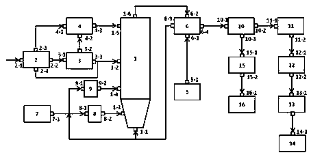
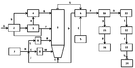
[0086] to combine figure 1 , 2 As shown, the oily sludge with low calorific value is used as raw material, the water content is 85%, the calorific value is 1500kcal / kg, and the sludge treatment capacity is 9 t / h.

[0087] The oily sludge incineration process is as follows:

[0088] 1) The oily sludge raw material A from the source of oily sludge is loaded into the sludge receiving system 2, and then transported to the sludge tank storage system 3 for storage. The odor B volatilized by the system 3 is collected by the odor collection / pressurization system 4 and discharged from the odor collection / pressurization system 4;

[0089] 2) 20000 Nm generated by the pressurized combustion air supply system 5 3 The low-temperature pressurized air C at 25°C and 0.3 MPa / h enters the pressurized combustion air preheating system 6, and the 850°C, 0.3 MPa, nitrogen oxide content from the fluidized bed incinerator (incinerator for short) 1 Exchange heat for 820 ppm high-temperature pressu...

Embodiment 2

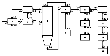
[0102] In this example, the oily sludge with high heat value is used as raw material, the water content is 70%, the heat value is 3000 kcal / kg, and the sludge treatment capacity is 5 t / h, so the fuel supply system is not included in Example 2 7. The first burner 8, the second burner 9, combined image 3 , 4 Shown:

[0103] The oily sludge incineration process is as follows:

[0104] 1) The oily sludge raw material A from the source of oily sludge is loaded into the sludge receiving system 2, and then transported to the sludge tank storage system 3 for storage. The odor B volatilized by the system 3 is collected by the odor collection / pressurization system 4 and discharged from the odor collection / pressurization system 4, and the discharged odor B enters the incinerator 1 for incineration (after the incinerator starts);

[0105] 2) 20000 Nm generated by the pressurized combustion air supply system 5 3 The pressurized air C at 25°C and 0.5 MPa / h enters the pressurized combus...


PUM


Abstract

The invention discloses an oil-containing sludge incineration system for a pressurized fluidized bed and an incineration treatment method. The process comprises the following steps: introducing preheated pressurized air into a fluidized bed incinerator, adding oil-containing sludge into the incinerator to pressurize and combust under a fluidized state, and supplementing auxiliary fuels to keep a combustion state stable if combustion heat is insufficient; enabling high-temperature pressurized wet flue gas generated in the incinerator to preheat pressurized air for combustion of the fluidized bed incinerator, preliminarily cooling the pressurized air into medium-temperature pressurized wet flue gas; continuously performing dust-removal denitration treatment on the flue gas to obtain medium-temperature pressurized clean wet flue gas, and recycling separated fly ash; recycling sensible heat of the medium-temperature pressurized clean wet flue gas through a waste heat recycling system, andrealizing up-to-standard emission through treatment such as a follow-up decompression system and a dehumidifying system. Reduction, harmless and resource utilization as well as energy conservation andemission reduction are realized on the oil-containing sludge, so that combustion efficiency can be greatly improved, equipment unit area processing ability is improved, and emission of harmful substances in flue gas is reduced.

Description

technical field [0001] The invention belongs to the technical field of oily sludge treatment, and in particular relates to a pressurized fluidized bed oily sludge incineration system and an incineration treatment method thereof. Background technique [0002] Oily sludge is mainly oil sludge and oil sand produced by petroleum exploration and development industry and petrochemical industry. A large amount of water treatment agent added. Oily sludge has the characteristics of large volume, large volume, high oil content, difficult treatment, and few comprehensive utilization methods. If it is not treated, it will pollute the environment. In addition, sludge contains a large amount of oily substances, which is also a kind of Important resources, if not recycled, will cause waste of resources. Therefore, oily sludge must be reduced, harmless and recycled. [0003] At present, the treatment methods of oily sludge mainly include the following types: landfill method, conditioning...

Claims


Application Information

Patent Timeline
Patent Type & Authority Applications(China)
IPC IPC(8): F23G7/00F23G7/06F23G5/12F23G5/30F23G5/44F23G5/46F23J15/00F23J15/02F23J15/06F23K5/00F23L5/00F23L15/00
CPCF23G7/00F23G7/06F23G5/448F23G5/30F23G5/46F23G5/12F23L5/00F23L15/00F23K5/00F23J15/006F23J15/02F23J15/025F23J15/06F23G2204/103F23G2206/10F23G2209/12Y02E20/34
Inventor 杜宏德张战国田伟民王涛刘周恩余剑
Owner 陕西正本环境工程有限公司
Learn More