
Bionic trunk fiber reinforced concrete beam and column structure

A fiber reinforced concrete, beam-column structure technology, applied in the field of concrete beam-column, can solve problems such as unparalleled anti-corrosion and protection performance

Inactive Publication Date: 2019-10-22
TAIYUAN UNIV OF TECH
View PDF5 Cites 2 Cited by
  • Summary
  • Abstract
  • Description
  • Claims
  • Application Information

AI Technical Summary

Problems solved by technology

The polyurea coating is more than flexible, full of rigidity, and rich in color. It is dense, continuous, and seamless, completely isolated from the infiltration of moisture and oxygen in the air, and has unparalleled anti-corrosion and protection properties.

Method used


Image

  • Bionic trunk fiber reinforced concrete beam and column structure
  • Bionic trunk fiber reinforced concrete beam and column structure
  • Bionic trunk fiber reinforced concrete beam and column structure

Examples


Embodiment 1

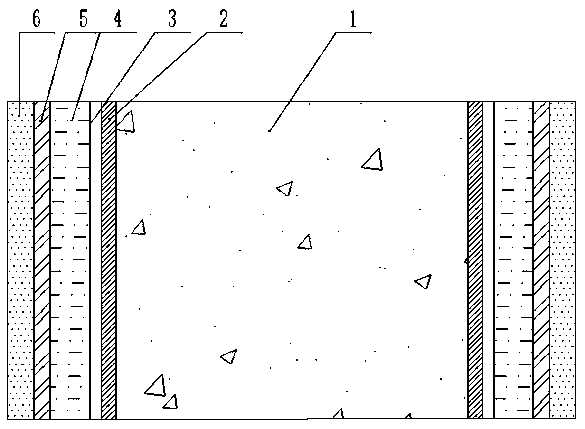
[0029] Such as figure 1 and figure 2 As shown, it is a "carbon fiber-polyurea" double-constrained non-prefabricated (Type II) fiber concrete (C-P-C) beam-column structure based on the bionic design idea of ​​​​trunk structure. From the inside to the outside, the fiber concrete core 1, Primer layer 2, leveling layer 3, polyurea middle layer 4, impregnating resin 5 and carbon fiber outer layer 6. The section of the fiber concrete core 1 can be circular or square, and steel bars can be configured according to engineering needs. Apply the primer layer 2 evenly on the outside of the fiber concrete core 1 with a roller brush. The amount of application depends on the type of primer and the surface condition of the concrete. When the concentration of the primer is low, the general dosage standard is 0.25-0.3kg / ㎡ . After the primer layer 2 is dried, apply repair glue to the concrete surface as a leveling layer 3, and the general dosage of the repair glue is 0.5-1.5kg / m 2 . After ...

Embodiment 2

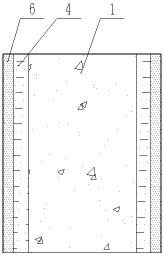
[0031] Such as image 3 and Figure 4 As shown, it is a "carbon fiber-polyurea" double-constrained prefabricated (type I) fiber concrete (C-P-C) beam-column structure based on the bionic design idea of ​​trunk structure, including fiber concrete core 1, polyurea middle layer 4 and The carbon fiber outer layer 6 uses a CFRP composite pipe as the carbon fiber outer layer 6, and sprays polyurea elastomer with a uniform thickness on the inner wall of the CFRP pipe as the polyurea intermediate layer 4, and the spraying thickness can be adjusted between 0.5mm-10mm. After the polyurea gel is hardened, the fiber concrete is poured inside the pipe body and cured.

[0032] Compared with the traditional steel-concrete composite structure, the C-P-C composite member designed based on the characteristics of the trunk structure "woody matrix + cambium + active phloem" can derive diverse mechanical properties and durability. The advantages and positive effects of embodiments 1 and 2 are sp...


PUM


Abstract

The invention relates to concrete beams and columns and discloses a carbon fiber-polyurea double-constraint fiber reinforced concrete beam and column structure based on a trunk structure bionic designconcept. The beam and column structure comprises a fiber reinforced concrete core, a bonding layer, a polyurea middle layer, an impregnating resin layer and a carbon fiber outer layer from inside tooutside in sequence. The carbon fiber outer layer and the polyurea middle layer constrain the inside fiber reinforced concrete core structure, thereby jointly forming a beam and column strengthened structure. The fiber reinforced concrete core and the polyurea middle layer are integrated through the bonding layer, and the carbon fiber outer layer is bonded to the outside of the polyurea middle layer through the impregnating resin layer. According to the structure, a bionic trunk structure is adopted for strengthening and optimizing the concrete structure, compared with a traditional steel-concrete combined structure, a C-P-C combined component designed based on the characteristics of wooden substrate, forming layer and active phloem of the trunk structure can derive diversified mechanicalperformance and durability.

Description

technical field [0001] The invention relates to concrete beams and columns, in particular to a "carbon fiber-polyurea" double-constrained fiber concrete (C-P-C) beam-column structure based on the idea of ​​tree trunk structure bionic design. Background technique [0002] Most of the current building beams and columns are reinforced concrete structures or steel structures. Concrete is a heterogeneous brittle material. When a small longitudinal deformation occurs, the deformation of various materials in the matrix is ​​inconsistent, which makes the concrete beams and columns crack due to the Poisson's ratio effect. The brittle failure of concrete limits the further development of concrete in engineering applications. Moreover, concrete is an important building material, and the durability protection of concrete structures is also an important issue. [0003] Carbon fiber (CF for short) is a new type of fiber material with high strength and high modulus fibers with a carbon co...

Claims


Application Information

Patent Timeline
IPC IPC(8): E04G23/02
CPCE04G23/0218
Inventor 张玉马志宏马钢刘玉军王志勇张循当王志华
Owner TAIYUAN UNIV OF TECH
Learn More