Defoaming injection device and delayed coking drum device
An injection device and defoaming technology, which is applied in the petroleum industry, cracking, non-catalytic thermal cracking, etc., can solve the problems such as the influence of the normal operation of the fractionation tower on the processing capacity of the coke tower, the coking blockage of oil and gas pipelines, and the increase in the amount of coke powder carried.
- Summary
- Abstract
- Description
- Claims
- Application Information
AI Technical Summary
Problems solved by technology
Method used
Image

Examples
Embodiment 1
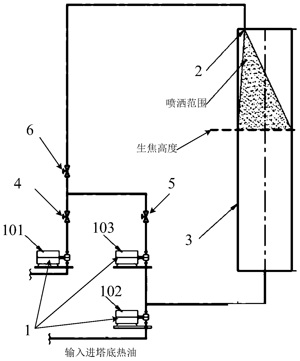
[0037] Such as figure 1 As shown, the invention discloses a defoaming injection device. Wherein, the defoaming injection device includes a defoaming agent supply assembly 1 and a spraying part 2 .
[0038] The sprinkler 2 is installed in the coke tower 3, and the sprayer 2 can be any structure that can completely cover the top surface of the coke in the coke tower 3 with the defoamer, for example, it can be an atomizing nozzle or a plurality of through holes evenly distributed board.
[0039] The defoamer supply assembly 1 provides defoamer to the sprinkler 2 , and the defoamer sprayed from the sprayer 2 can completely cover the top surface of the coke in the coke drum 3 .
[0040] In the defoaming injection device disclosed in the present invention, when the coke height in the coke tower 3 reaches the normal height position, the defoamer supply assembly 1 starts to provide the spraying part 2 with defoaming agent, so that the sprayed part 2 sprays The defoamer can complete...
Embodiment 2
[0042] In the second embodiment provided by the present invention, the structure of the defoaming injection device in this embodiment is similar to the structure of the defoaming injection device in the first embodiment, and the similarities will not be repeated, and only the differences will be introduced.
[0043] In this embodiment, the present invention specifically discloses that the spraying member 2 is an atomizing nozzle, and the atomizing nozzle can atomize and spray the defoamer into the coke drum 3 . Using the atomizing nozzle, the defoamer can be atomized into extremely fine mist droplets, and the mist liquid sprayed out through the atomizing nozzle can fully contact with the oil and gas, eliminating the phenomenon of dripping and dripping, which can greatly improve the gas-liquid contact efficiency.
[0044] Further, the present invention discloses that the atomizing nozzle is installed on the inner top of the coke tower 3, so as to facilitate downward spraying of ...
Embodiment 3
[0058] In the third embodiment provided by the present invention, the structure of the defoaming injection device in this embodiment is similar to the structure of the defoaming injection device in the second embodiment, so the similarities will not be repeated, and only the differences will be introduced.
[0059] In this embodiment, the present invention discloses that the spraying member 2 is a spraying plate, and the spraying plate is clamped on the coke tower 3. The spraying plate can be arranged perpendicular to the axis of the coke tower 3, or can be installed at a certain angle. In addition, there are a plurality of spray through holes evenly distributed on the spray plate, and the defoamer falls onto the spray plate through the entrance of the coke tower 3, and is evenly sprayed into the coke tower 3 through the spray plate.
[0060] Lead one path of hot oil from the outlet of the hot oil pump 102, pass through the booster pump 103, mix with the defoamer, and pour into...
PUM
 Abstract
Description
Claims
Application Information
 - Generate Ideas
- Intellectual Property
- Life Sciences
- Materials
- Tech Scout
- Unparalleled Data Quality
- Higher Quality Content
- 60% Fewer Hallucinations
Browse by: Latest US Patents, China's latest patents, Technical Efficacy Thesaurus, Application Domain, Technology Topic, Popular Technical Reports.
© 2025 PatSnap. All rights reserved.Legal|Privacy policy|Modern Slavery Act Transparency Statement|Sitemap|About US| Contact US: help@patsnap.com