Steel pipe weld joint ultrasonic phased array detection device
An ultrasonic phased array and detection device technology, which is applied in measurement devices, analysis of solids using sonic/ultrasonic/infrasonic waves, and material analysis using sonic/ultrasonic/infrasonic waves, etc. Work difficulty, inconvenience, etc
- Summary
- Abstract
- Description
- Claims
- Application Information
AI Technical Summary
Problems solved by technology
Method used
Image
Examples
Embodiment 1
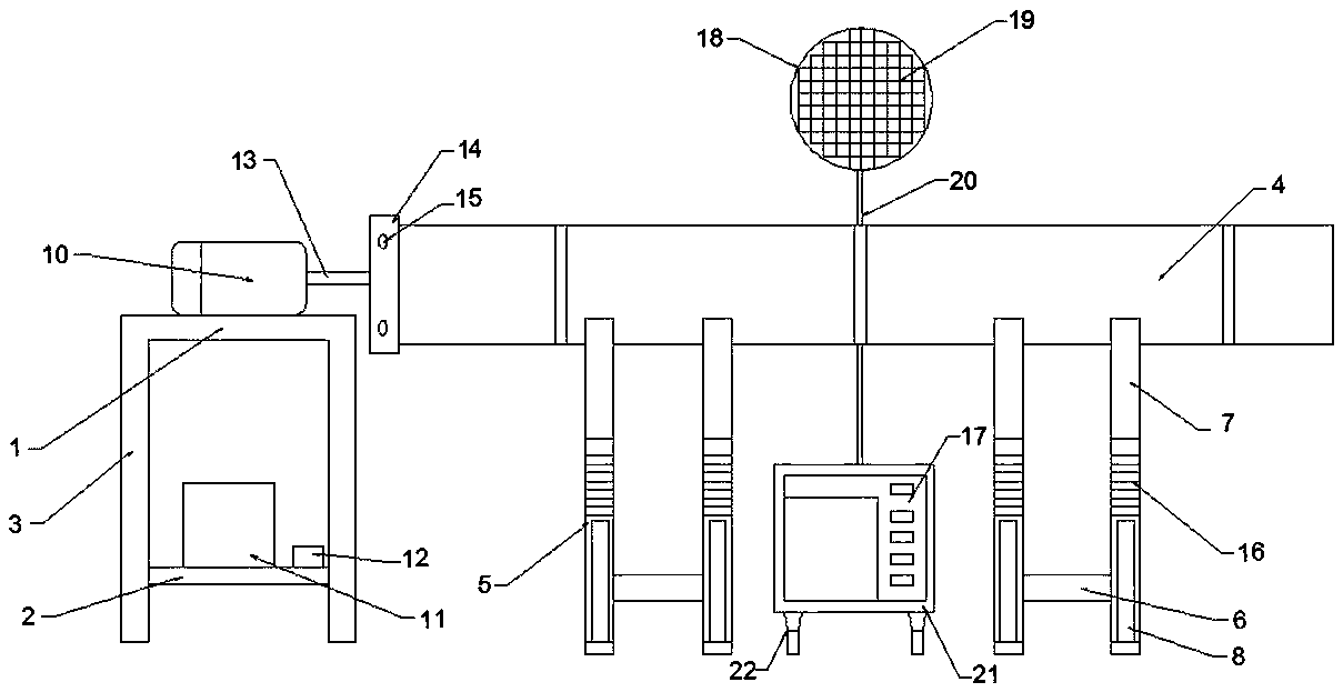
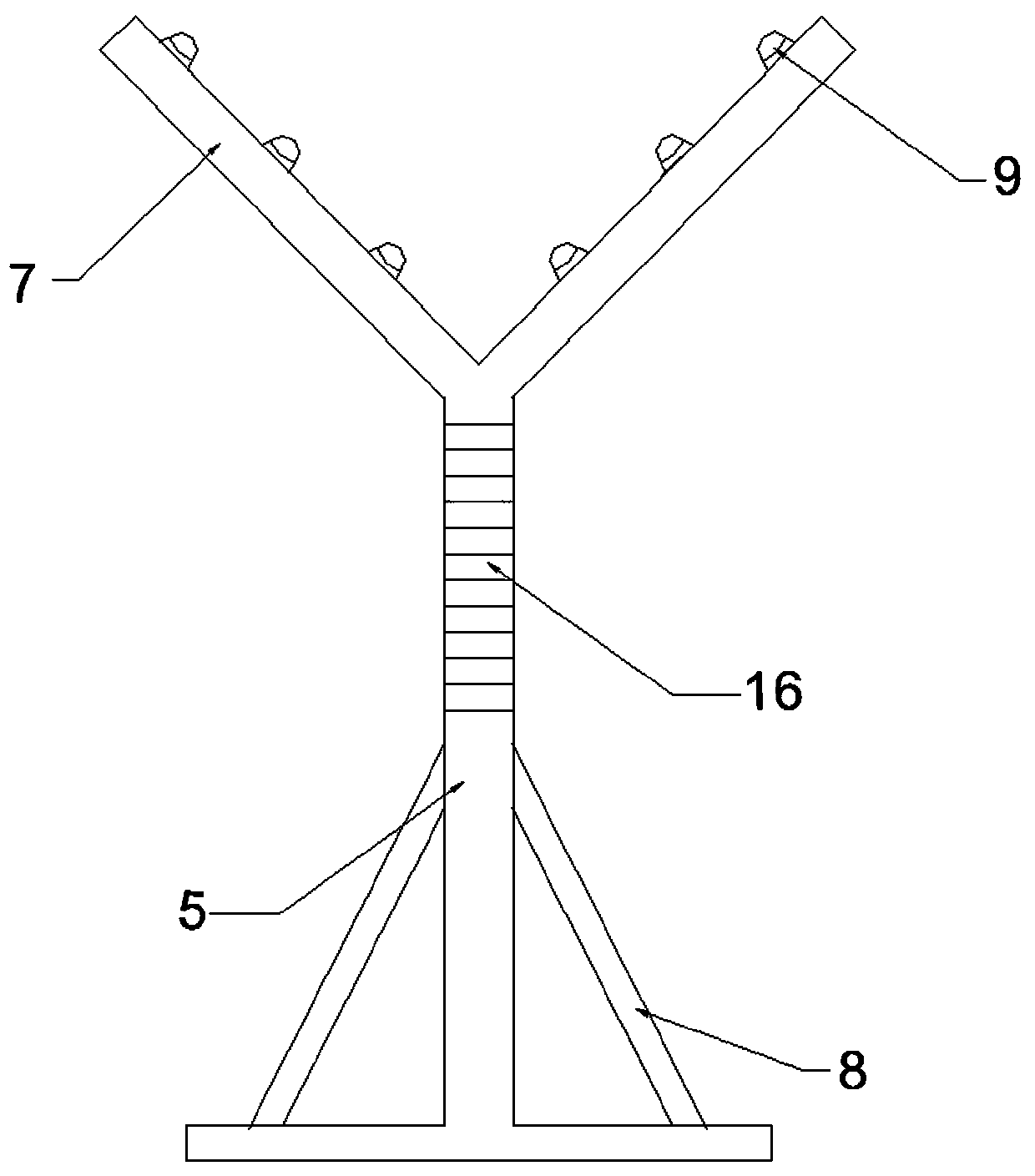
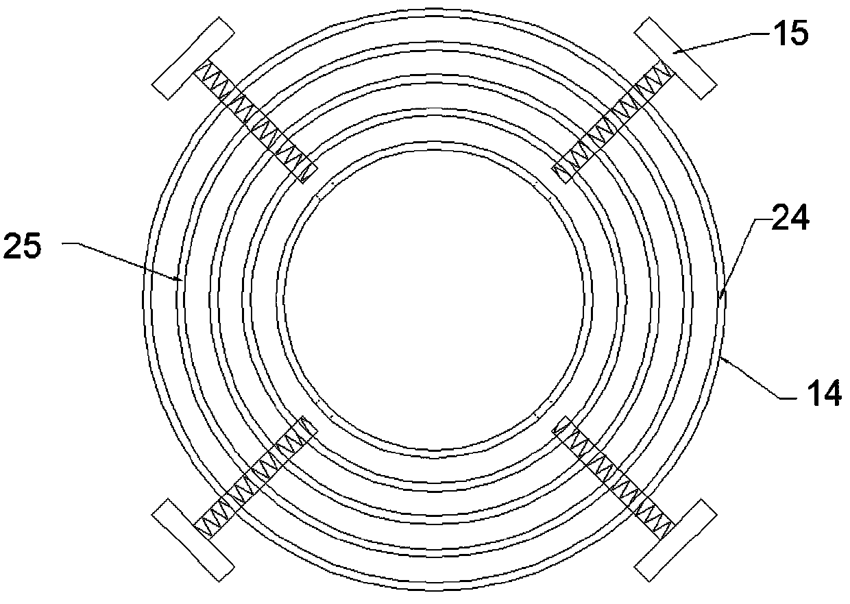
[0039] like Figure 1-4 It is the first embodiment of the present invention, an ultrasonic phased array detection device for steel pipe welds, including a support frame and an ultrasonic flaw detector 17, the support frame includes a first support frame and two second support frames, the first support The frame includes the upper plate 1 of the support frame and the lower plate 2 of the support frame. The four corners of the upper plate 1 of the support frame are vertically fixed with legs 3 by means of bolts or welding, and the support frame is horizontally installed between the legs 3 by means of bolts or welding Lower deck 2. The second bracing frame comprises two T-shaped frames 5, and the vertical bar of the T-shaped frame 5 is an electro-hydraulic push rod. On the vertical bar, a circular scale line-16 is engraved by a carving knife, which is used to represent the rising height of the vertical bar. Two Vertically fix the cross bar 6 by means of bolts or welding etc. bet...
Embodiment 2
[0045] like Figure 5-6 It is the second embodiment of the present invention, and the difference from the first embodiment is that the second support frame includes two parallel I-shaped frames 26 and cross bars vertically welded between the I-shaped frames 26 6. A plurality of card slots 28 are symmetrically provided on the I-shaped frame 26, and two round shafts 27 are snapped into the slots 28, and supporting wheels 9 are installed on the round shafts 27, and the supporting wheels 9 are ball bearings. The ball bearing includes a stator and a rotor, the circular shaft 27 is welded to the stator of the ball bearing, and the vertical bar of the I-shaped frame 26 is an electro-hydraulic push rod with scales, in order to improve the stability of the second support frame , four support rods 8 are fixed on the work frame 26 by means of bolts or welding. When it is necessary to detect the welds of the steel pipes 4 with different left and right diameters, the circular shaft 27 is ...
Embodiment 4
[0049] like Figure 8 Shown is the fourth embodiment of the present invention. The structure of this embodiment is basically the same as that of the first embodiment. Carve out the ring-shaped scale line 2 32 used to represent the rising height of the upper layer plate 1 of the support frame. When the relative position of the rotary chuck 14 and the steel pipe 4 needs to be fine-tuned, adjust the height of the output shaft 13 from the ground with reference to the scale on the leg 3. It is more convenient and fast to fix the rotary chuck 14 on the steel pipe 4 .
PUM
 Abstract
Description
Claims
Application Information
 - R&D
- Intellectual Property
- Life Sciences
- Materials
- Tech Scout
- Unparalleled Data Quality
- Higher Quality Content
- 60% Fewer Hallucinations
Browse by: Latest US Patents, China's latest patents, Technical Efficacy Thesaurus, Application Domain, Technology Topic, Popular Technical Reports.
© 2025 PatSnap. All rights reserved.Legal|Privacy policy|Modern Slavery Act Transparency Statement|Sitemap|About US| Contact US: help@patsnap.com


