
Automatic machining equipment for bearing outer ring

A technology of automatic processing and bearing outer ring, applied in the field of bearing processing, which can solve the problems of wasting site area, difficult to control the feeding accuracy, and reducing the friction coefficient.

Active Publication Date: 2019-10-11
苏州市东挺河智能科技发展有限公司
View PDF6 Cites 5 Cited by
  • Summary
  • Abstract
  • Description
  • Claims
  • Application Information

AI Technical Summary

Problems solved by technology

Its main function is to support the mechanical rotating body, reduce the friction coefficient during its movement, and ensure its rotation accuracy. The conventional processing process of the bearing outer ring is raw material, forging, annealing, turning, quenching, tempering, grinding and Assembling, and the grinding of the outer ring of the bearing is divided into outer ring grinding, outer groove grinding, outer groove superfine grinding and outer circle grinding. When the conventional bearing outer ring is processed, the factory often divides the outer ring grinding and outer groove grinding into two parts. A large amount of space is wasted for processing with one piece of equipment, and some factories also use manual feeding one by one. Because the workers are prone to fatigue, it is difficult to control the accuracy of the feeding, which makes the bearing processing more prone to accuracy errors.

Method used


Image

  • Automatic machining equipment for bearing outer ring
  • Automatic machining equipment for bearing outer ring
  • Automatic machining equipment for bearing outer ring

Examples


Embodiment Construction

[0028] The technical solutions of the present invention will be further described below in conjunction with the accompanying drawings and through specific implementation methods.

[0029] Wherein, the accompanying drawings are only for illustrative purposes, showing only schematic diagrams, rather than physical drawings, and should not be construed as limitations on this patent; in order to better illustrate the embodiments of the present invention, some parts of the accompanying drawings will be omitted, Enlargement or reduction does not represent the size of the actual product; for those skilled in the art, it is understandable that certain known structures and their descriptions in the drawings may be omitted.

[0030] In the drawings of the embodiments of the present invention, the same or similar symbols correspond to the same or similar components; , "inner", "outer" and other indicated orientations or positional relationships are based on the orientations or positional ...


PUM


Abstract

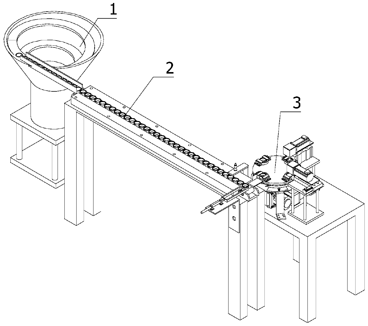
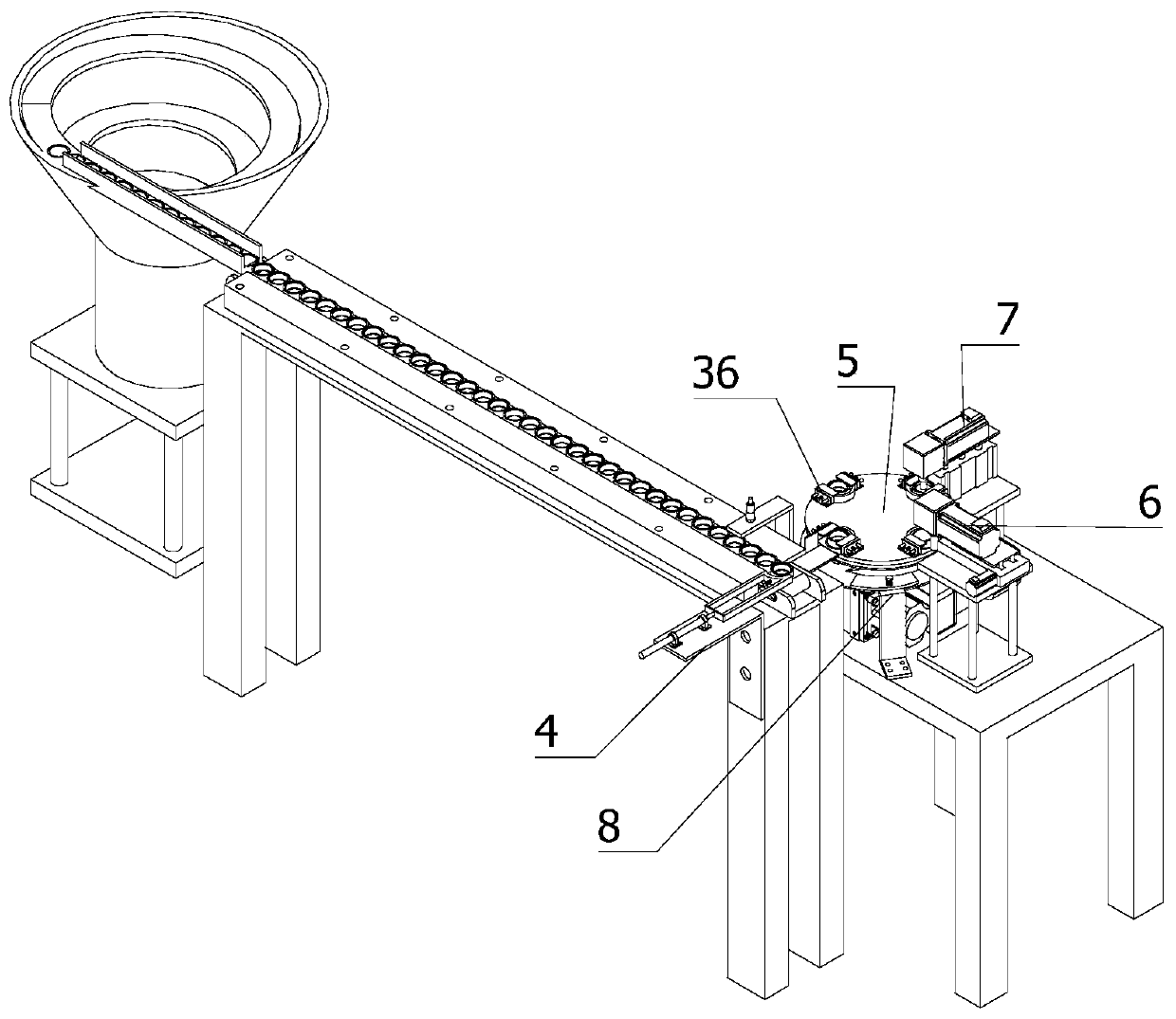
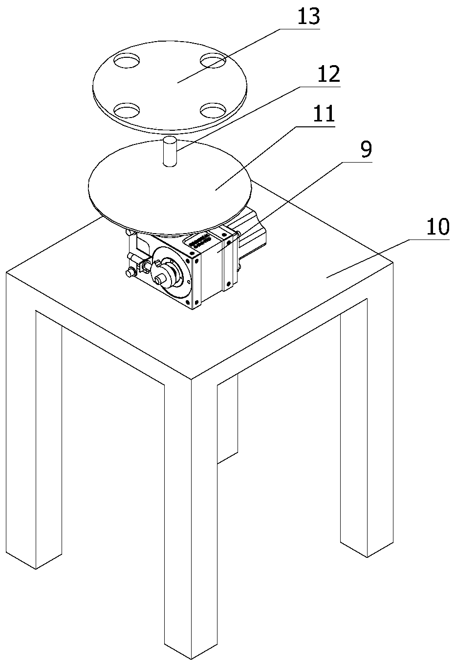
The invention relates to the field of bearing machining, in particular to automatic machining equipment for a bearing outer ring. The equipment comprises a vibration disc, a conveying belt and a machining mechanism, wherein the end, far away from the vibrating disc, of the conveying belt is provided with a pushing mechanism, the machining mechanism comprises a rotating mechanism, a ring grinding mechanism, a groove grinding mechanism and a pushing mechanism, the rotating mechanism comprises a cam cutting machine, a first supporting frame, a rotating disc, a rotating rod and a rotating table, the rotating disc is arranged at the top of the cam cutting machine, the rotating rod is fixedly arranged at the top of the rotating disc, the pushing mechanism is located between the rotating disc andthe rotating table, and the pushing mechanism, the ring grinding mechanism and the groove grinding mechanism are sequentially distributed along the circumferential direction of the rotating table. According to the automatic machining equipment for the bearing outer ring, outer ring grinding and outer groove grinding are simultaneously conducted by adopting the mechanism, the waste of a large quantity of area of sites is reduced, the automatic feeding mode of the vibrating disc and the mode of automatic alignment of conical ejector pins are adopted, so that the precision of feeding is controlled, and the machining precision of the bearings is more accurate.

Description

technical field [0001] The invention relates to the field of bearing processing, in particular to an automatic processing equipment for bearing outer rings. Background technique [0002] Bearings are an important part of contemporary mechanical equipment. Its main function is to support the mechanical rotating body, reduce the friction coefficient during its movement, and ensure its rotation accuracy. The conventional processing process of the bearing outer ring is raw material, forging, annealing, turning, quenching, tempering, grinding and Assembling, and the grinding of the outer ring of the bearing is divided into outer ring grinding, outer groove grinding, outer groove superfine grinding and outer circle grinding. When the conventional bearing outer ring is processed, the factory often divides the outer ring grinding and the outer groove grinding into two parts. A lot of space is wasted for processing with one device, and some factories also use manual feeding one by o...

Claims


Application Information

Patent Timeline
IPC IPC(8): B24B41/00B24B5/35B24B27/00B24B19/06B24B5/04B24B41/06B24B47/12
CPCB24B27/0023B24B41/005B24B47/12
Inventor 朱海艳
Owner 苏州市东挺河智能科技发展有限公司
Learn More