Pupillary light reflex diagnosis device in neurology department and application thereof
A light reflection and diagnostic device technology, applied in the field of medical equipment, can solve the problems of inconvenient diagnosis, inconvenient recording, and difficult diagnosis, etc., achieve good operability and portability, avoid control errors, and accurately diagnose and record. Effect
- Summary
- Abstract
- Description
- Claims
- Application Information
AI Technical Summary
Problems solved by technology
Method used
Image
Examples
Embodiment 1
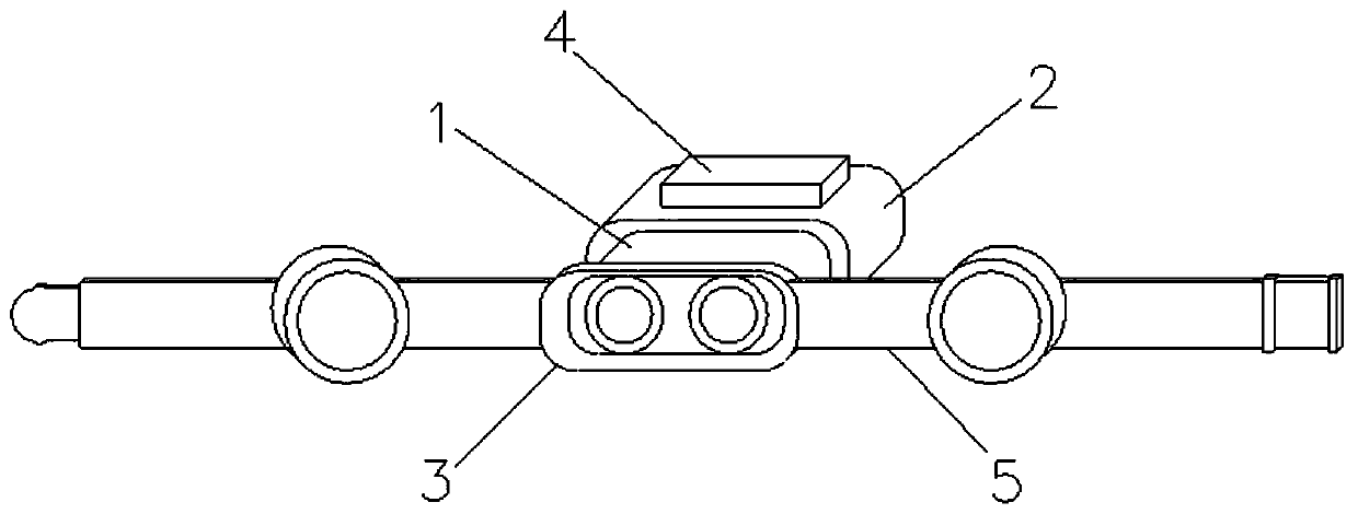
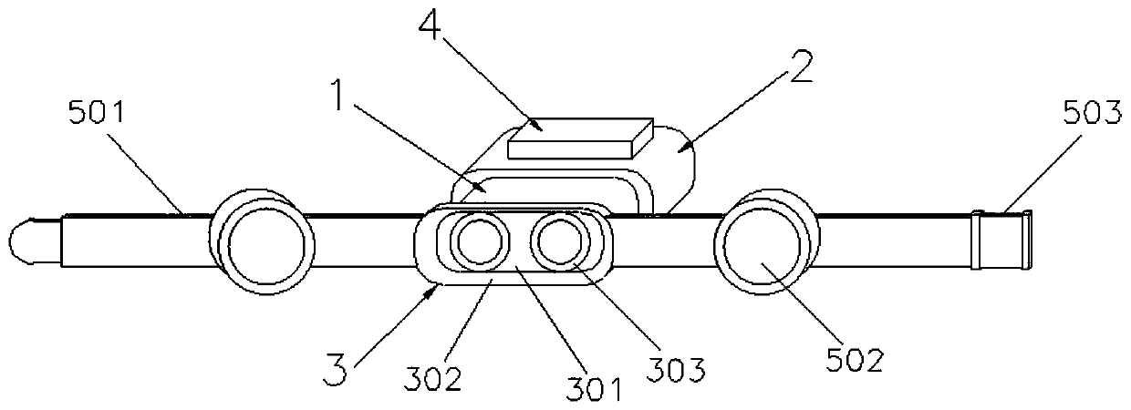
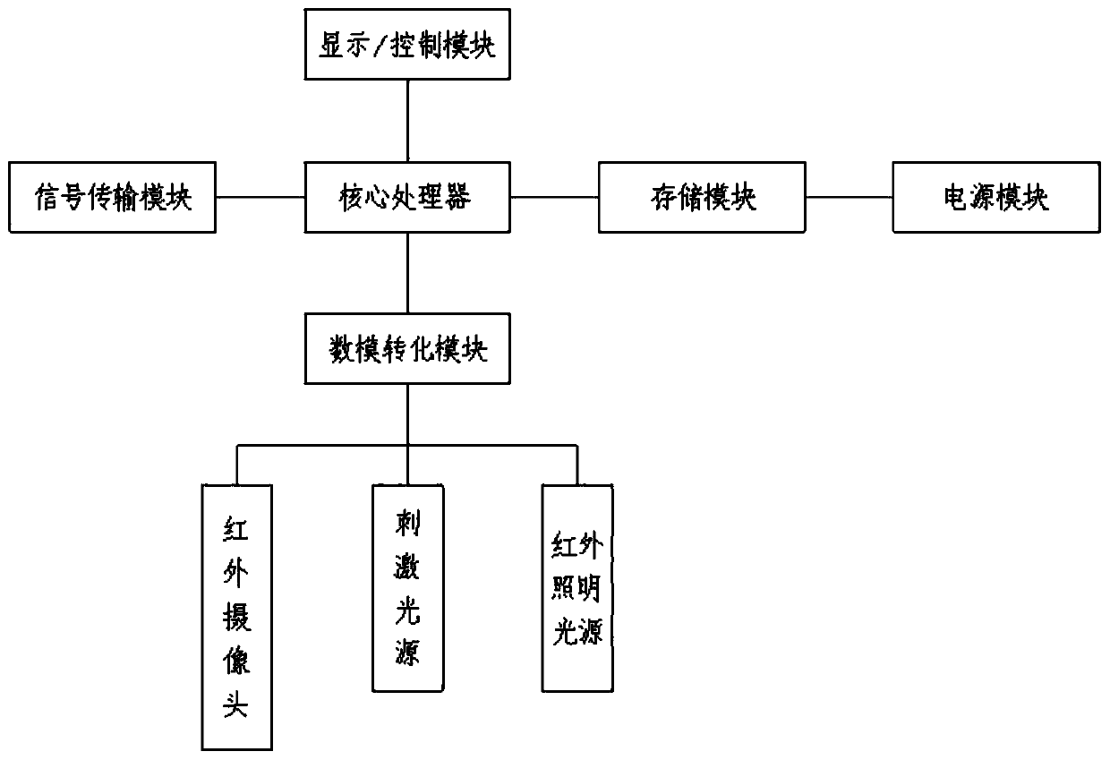
[0040] Such as Figure 1-3 shown
[0041] A device for diagnosing pupillary light reflex in neurology. The main body is integrally formed and fixed to the eye with a fixing belt. The front end is the eye contact part 3 that contacts the eye and fully closes the eye. The image acquisition part 1 and the stimulating light source part 2 are installed, and both are connected with the control part 4 installed on the stimulating light source part 2;
[0042]The eye contact part 3 includes a base 301. The base 301 is a rectangular parallelepiped with smooth corners, and a through hole 303 corresponding to the eye is opened inside. The periphery of the through hole 303 is covered with a ring of elastic washers, and the outer wall of the front end is covered with a layer of The high-density sponge 302 that fits the outline of the human eye seals the eye area, and the surface is painted black. The rear end of the eye contact part 3 is installed with an integrally formed image acquisiti...
Embodiment 2
[0052] A method for using a device for diagnosing pupillary light reflex in neurology, comprising the following steps:
[0053] Step 1. Wear the pupillary light reflex diagnostic device on the patient's eyes through the fixing belt
[0054] Put the through hole part of the eye contact part on the eye end to cover, and the rear end is fixed by the connecting buckle of the fixing belt. At the same time, adjust the earmuffs to cover the ear, and adjust it to an appropriate tightness to ensure contact with the eye. The part will not leak light;
[0055] Step 2. Pre-correction of pupillary light reflex
[0056] Adjust the photoreflex diagnostic device so that the pupils of both eyes of the subject are located in the center of the display window, so that the stimulus light source and the center of the pupils are in a straight line during the examination;
[0057] Step 3. Detection of pupillary light reflex
[0058] Set the parameters of the infrared camera, stimulus light source ...
Embodiment 3
[0064] The application of a neurology department pupillary light reflex diagnosis device in the neurology department pupillary light reflex diagnosis.
[0065] First get rid of whether the test patient has used medicine in the whole body or the eyes locally in the near future, so that the reflection of the pupil is affected. Before the examination, the patient closed his eyes and had a quiet rest for 5 minutes. When the device is worn, the device is similar to VR, mainly including eye contact parts, image acquisition parts, stimulating light source parts and control parts. For the eyes, automatic pupillary light reflex diagnosis is realized, without manual operation, and control errors in the manual operation process are avoided;
[0066] Then observe through the display screen according to the above operation method, adjust the eye position of the subject so that the pupils of both eyes are respectively located in the display / control module, check the alternate stimulation mo...
PUM
 Abstract
Description
Claims
Application Information
 - R&D Engineer
- R&D Manager
- IP Professional
- Industry Leading Data Capabilities
- Powerful AI technology
- Patent DNA Extraction
Browse by: Latest US Patents, China's latest patents, Technical Efficacy Thesaurus, Application Domain, Technology Topic, Popular Technical Reports.
© 2024 PatSnap. All rights reserved.Legal|Privacy policy|Modern Slavery Act Transparency Statement|Sitemap|About US| Contact US: help@patsnap.com


