Flat panel CT (computed tomography) machine

A flat-panel and flat-panel detector technology, which is applied in medical science, equipment for radiological diagnosis, diagnosis, etc., can solve problems such as long time, unsatisfactory images, and large doses of radiation to patients

Inactive Publication Date: 2019-09-27
刘洪斌
View PDF0 Cites 2 Cited by
  • Summary
  • Abstract
  • Description
  • Claims
  • Application Information

AI Technical Summary

Problems solved by technology

[0005] 1. The number of detector rows is limited, so that the scanning range of 360°rotational scanning is relatively narrow (now the widest vertical detector is 160mm, which can basically meet the single-turn scanning requirements of small parts, but still cannot meet the single-turn scanning requirements of large parts. circle scanning requirements), it takes multiple circles of helical scanning to complete a part, and the bed is moving during scanning, which is easy to form motion artifacts
[0006] 2. Because of the helical scanning, the scanned 360° image is not a real cross-sectional image, but a cross-sectional image with a certain layer thickness that is not on the same section plane, although the current 256 rows can already achieve a layer thickness of 625um (the thinnest 400um ), but it is not an isometric image after all; there is an interlayer gap, although the current 256 rows can also give a 625um (thinnest 400um) thick interlayer gap image through the algorithm, but it is not a real image after all
There is a possibility of missed detection of early very subtle lesions
[0007] 3. The scanning time is long; the radiation dose of the patient is also large
Due to the need for multiple scans, it takes a long time; it also leads to an increase in the dose of radiation exposure to the patient
[0008] 4. The spatial resolution is low, and the pixels of the reconstructed image are not high
However, the single-side size of the medical flat panel detectors used for DR and DSA on the market is up to 17 inches (about 43cm), which can fully meet the needs of use, but if it is to be applied to a flat-panel CT machine, the size is still too small to be used in the horizontal direction. The abdomen and chest are included in the scanning range; at the same time, the images obtained after trying are not ideal, and no effective solution has been found so far, so it cannot be promoted to the market

Method used


Image

  • Flat panel CT (computed tomography) machine

Examples


Embodiment 1

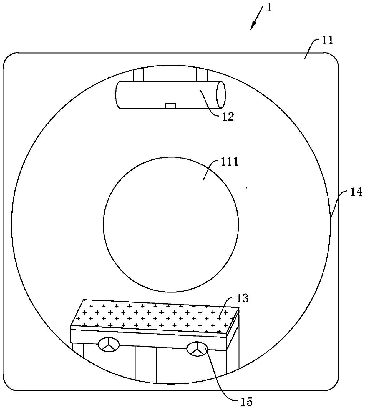
[0045] Such as figure 1 As shown, this embodiment provides a scanning frame 1 of a flat-panel CT machine, including a frame 11 , a radiation emitter 12 , a flat-panel detector 13 , a rotating device 14 and a cooling device 15 .

[0046] An inner hole 111 is formed on the frame 11 , and the radiation emitter 12 and the flat panel detector 13 are relatively arranged in the rotating device 14 and can be driven by the rotating device 14 to move along the axis of the inner hole 111 on a circle.

[0047] In this embodiment, the flat-panel CT machine adopts a 360° scanning mode, and the general structure of the scanning frame 1 is similar to that of the existing third-generation CT machine. In other embodiments, the flat-panel CT machine can also adopt a 180° scanning mode. At this time, its scanning frame 1 can be made into various C-arm structures in addition to a structure similar to that of a traditional CT machine.

[0048] In this embodiment, the scanning frame 1 is the main b...


PUM


Abstract

The invention provides a flat panel CT (computed tomography) machine. The flat panel CT machine comprises a ray emitter and a flat panel detector, wherein the ray emitter adopts 360-degree or 180-degree scanning; the length of the flat panel detector in the axial direction perpendicular to circular motion of the flat panel detector is larger than 17 inches. The flat panel detector has larger length and width than a flat panel detector for DSA, can cover single part of the human body and requires no helical scanning. A bed does not move during scanning, the scanning time is substantially reduced, and motion artifact can be effectively reduced; the irradiation dosage of patients can be substantially reduced; the spatial resolution and longitudinal scanning layer number are substantially increased, gapless scanning is realized, and missing examination can be ensured. An X-ray emission pulse control technology is adopted, trailing and afterglow are avoided, so that data obtained by the CT machine are more real, and images are clearer. By use of the pulse control technology or semi-circle scanning manner, the scanning frequency is halved, and the flat panel CT machine has the possibility of actual application by redesigning the element number of the detector.

Description

technical field [0001] The invention relates to the technical field of CT equipment, in particular to a flat-panel CT machine. Background technique [0002] CT (Computed Tomography), that is, computerized tomography. The basic principle of existing CT imaging is to use X-ray beams to scan a layer of a certain thickness of the human body inspection site. The X-rays that pass through this layer are received by the detector and converted into visible light. The analog / digital converter (analog / digital converter) converts the digital signal into a computer for processing. The processing of image formation is like dividing the selected layer into several cuboids with the same volume, which are called voxels. The scanned information is calculated to obtain the X-ray attenuation coefficient or absorption coefficient of each voxel, and then arranged into a matrix, that is, a digital matrix. Numerical matrices can be stored on disk or CD. Through the digital / analog converter, eac...

Claims


Application Information

Patent Timeline
IPC IPC(8): A61B6/03
CPCA61B6/032A61B6/035A61B6/4441A61B6/466A61B6/5264
Inventor 刘洪斌
Owner 刘洪斌
Why Eureka
Try Eureka