
Sewage anaerobic reactor

An anaerobic reactor and anaerobic reaction technology, applied in the direction of gas production bioreactor, bioreactor/fermenter combination, anaerobic digestion treatment, etc., can solve the problem of poor slagging effect of anaerobic reactor, and achieve Improve the effect of slag discharge, reduce pollution and reduce the effect of grinding

Inactive Publication Date: 2019-09-24
台州市永丰纸业有限公司
View PDF10 Cites 2 Cited by
  • Summary
  • Abstract
  • Description
  • Claims
  • Application Information

AI Technical Summary

Problems solved by technology

However, after the bacteria slime produces calcification and hardening, it precipitates in the bottom of the reactor in the form of particles. Even if there is a water distribution device to flush inward during cleaning, this design makes the bacteria sludge agglomerated particles scattered in the reaction after precipitation. At the bottom of the device, it is difficult to push these hardened bacteria sludge particles towards the discharge port of the sewage pipe by the flushing effect of the water distribution device alone. During cleaning, the suction force when the water is discharged is mainly used to take away the agglomerates, so that only the water can be discharged. A small part, resulting in poor slagging effect of the anaerobic reactor

Method used

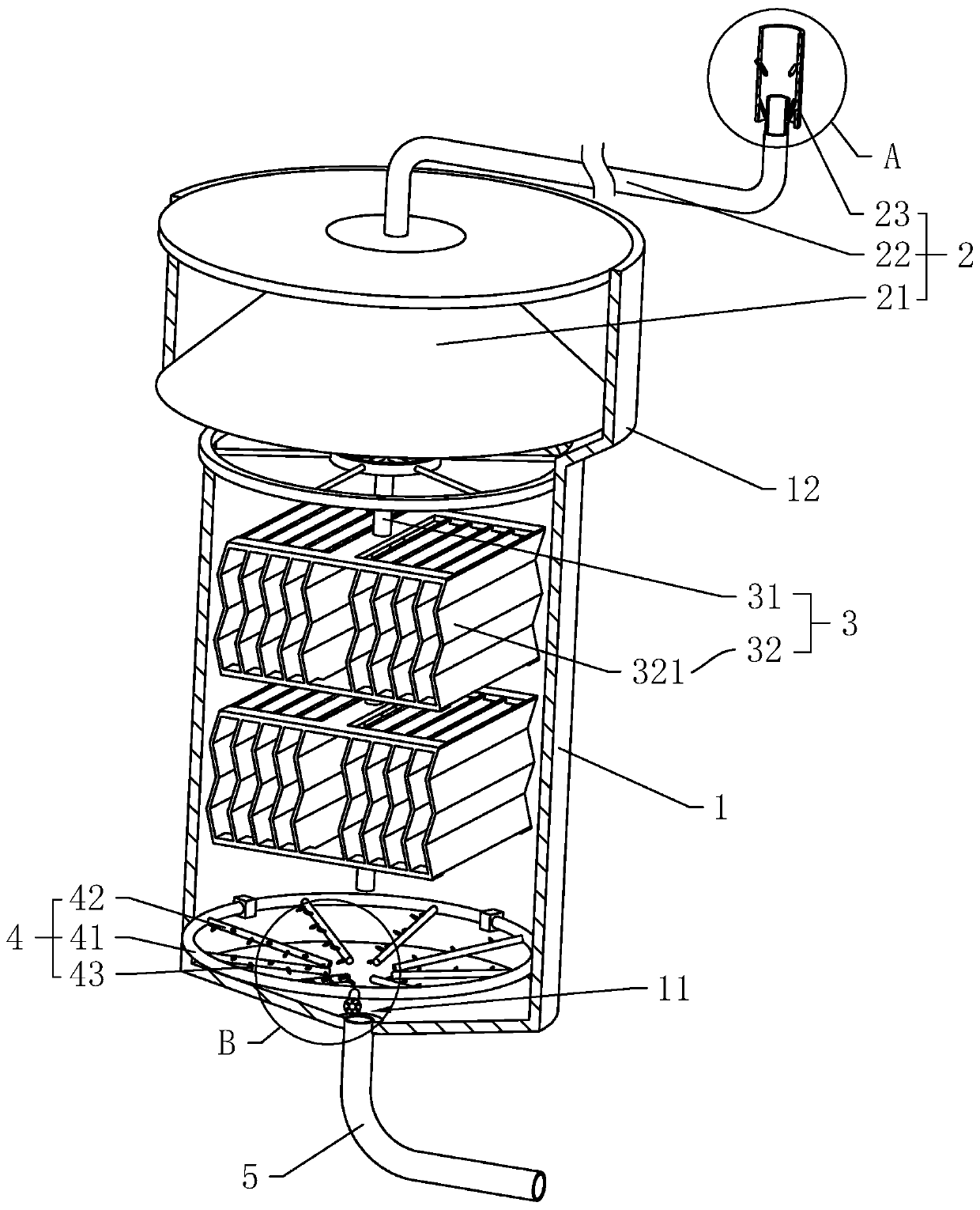

Image

  • Sewage anaerobic reactor
  • Sewage anaerobic reactor
  • Sewage anaerobic reactor

Examples


Embodiment Construction

[0036] The present invention will be described in further detail below in conjunction with the accompanying drawings.

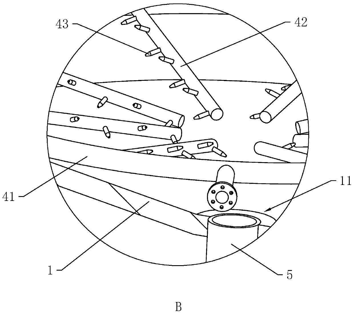
[0037] Such as figure 1 As shown, a sewage anaerobic reactor includes a tower body 1, a water distribution device 4, and a sewage pipe 5. The tower body 1 is cylindrical, and the inner bottom of the tower body 1 is conical. The conical structure makes the tower body A funnel-shaped sediment sink 11 is formed at the inner bottom of the tower body 1, and the conical surface at the inner bottom of the tower body 1 is set at an angle of 19° from the horizontal plane.

[0038] The inclination angle of the inner bottom of the tower body 1 is set according to the size of the tower body 1. In general, like an anaerobic device used in a paper mill, the diameter of the tower body 1 is generally about 5m, and the tower height is generally about 20m, while 19° According to the calculation of tan19°=h / r=0.34, the thickness of the cushion layer at the inner bottom of the ...


PUM


Abstract

The invention discloses a sewage anaerobic reactor, and relates to a sewage treatment device. The sewage anaerobic reactor is used for solving the problem of a poor slag discharging effect of common reactors. The sewage anaerobic reactor comprises a tower body, a water distribution device which is arranged in the tower body and at the bottom of the tower body and a sewage discharging pipe which is arranged at the bottom of the tower body in a communication mode, wherein the bottom of the tower body is of a conical shape, a funnel-shaped slag setting trap mouth is formed in the bottom of the tower body due to the conical structure, the sewage discharging pipe communicates with the lowest point of the slag setting trap mouth, and the water inlet direction of the water distribution device is in the tangential direction of the tower body. The sewage anaerobic reactor has the following advantages and effects that water distribution branch pipes in the water distribution device are distributed in an annular shape along the sewage discharging pipe, and rotary turbulent flow is formed in the tower body when water is introduced through the water distribution branch pipes, so that agglomeration at the bottom of the tower body is disturbed; and centred motion of the agglomeration is generated under the action of push flow, therefore the agglomeration is gathered at the center of the tower body, and then more of the gathered agglomeration can enter the sewage discharging pipe, so that the slag discharging effect of the reactor is improved.

Description

technical field [0001] The invention relates to sewage treatment equipment, in particular to a sewage anaerobic reactor. Background technique [0002] For the paper industry, since water is mainly used to form paper during the production process, a large amount of sewage will be generated, which contains a large amount of chemical components, heavy metals and bacteria. If it is discharged directly, it will cause serious pollution to the environment. Therefore, Pollution reduction treatment is required before discharge. [0003] Since calcium carbonate is sprayed on its surface during the papermaking process to enhance the strength of the paper, and the aqueous solution of pulp is acidic, some calcium carbonate will be dissolved, which leads to a large amount of calcium ions in the sewage generated by papermaking. When the sewage is introduced into the anaerobic reactor for treatment, it is a common problem in the industry that the sludge of active bacteria in the reactor is...

Claims


Application Information

Patent Timeline
IPC IPC(8): C02F3/28C12M1/107C12M1/00C02F103/28
CPCC02F1/006C02F3/28C02F2103/28C12M21/04C12M23/36C12M47/18
Inventor 周双
Owner 台州市永丰纸业有限公司
Learn More