
Composite electrical fire monitoring detector and monitoring method thereof

A technology for electrical fire and detectors, which is applied in the field of composite electrical fire monitoring detectors and its monitoring, can solve the problem of non-standard installation and wiring construction, failure to fully consider the load characteristics of the electrical circuit in the product use environment, and the alarm performance of the application requirements. Problems such as matching, function and performance cannot meet its application requirements

Pending Publication Date: 2019-09-20
SHENYANG FIRE RES INST OF MEM
View PDF0 Cites 3 Cited by
  • Summary
  • Abstract
  • Description
  • Claims
  • Application Information

AI Technical Summary

Problems solved by technology

Analysis of the main reasons can be summarized as follows: 1. At present, most electrical fire monitoring systems are installed only to meet the requirements of mandatory acceptance specifications, without fully considering the use environment of the product, the load characteristics of electrical circuits, application requirements and Product alarm performance matching and other issues
2. There is a widespread problem of lack of maintenance and management after product installation
3. The function and anti-interference ability of some products are insufficient
4. Problems arising from non-standard installation and wiring construction of products
The research results show that although the existing electrical fire detection products have been widely used, their functions and performance for specific places cannot meet their application requirements

Method used


Image

  • Composite electrical fire monitoring detector and monitoring method thereof
  • Composite electrical fire monitoring detector and monitoring method thereof
  • Composite electrical fire monitoring detector and monitoring method thereof

Examples


Embodiment approach

[0257] For residential buildings, old buildings, and urban public facilities, electrical fire monitoring requires more convenient and flexible installation and configuration solutions. It is difficult to construct traditional electrical fire monitoring detectors and monitoring equipment through wired connections, and the system must have The fire central control room is managed in a unified manner, and it is difficult to effectively centralize management due to scattered users. This solution is based on NB-IOT wireless communication technology and a good solution to the problem of installation and wiring. It solves the problem of user management through the Internet of Things platform and mobile APP, and also facilitates the provision of data support for the operating status of the monitored line. Specific real-time method reference Figure 5 and corresponding instructions.


PUM


Abstract

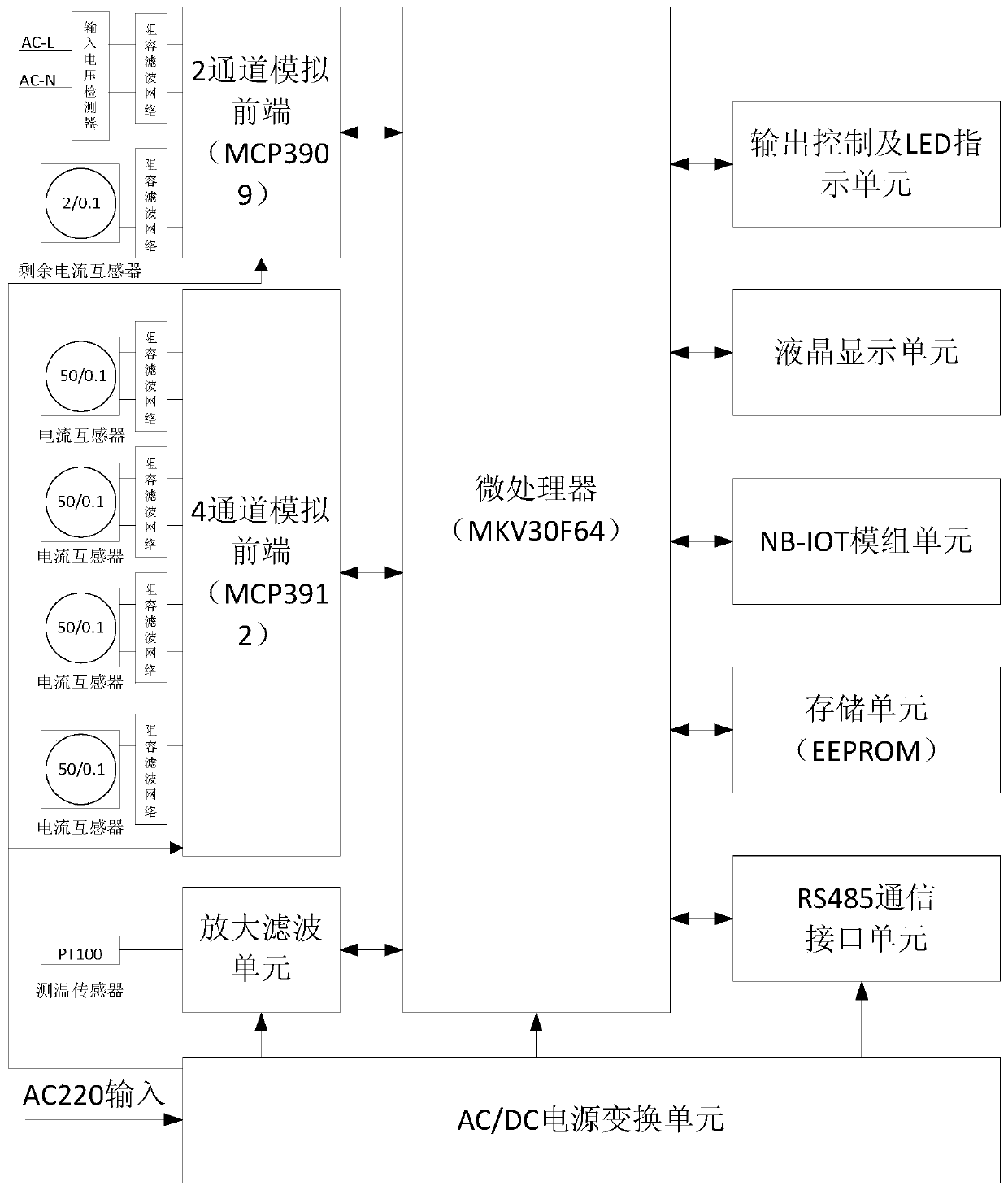
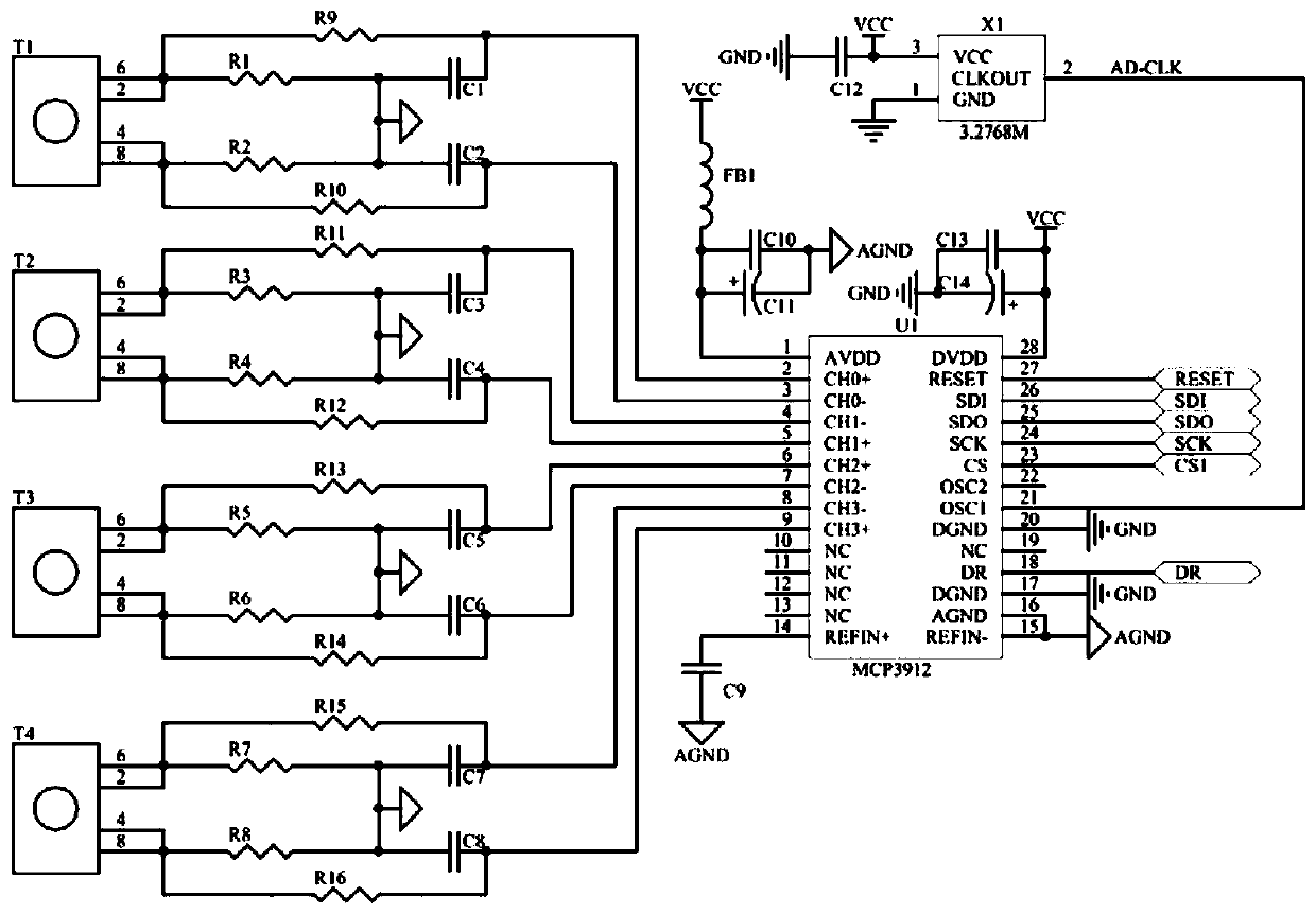
The invention provides a composite electrical fire monitoring detector and a monitoring method thereof. The monitoring detector comprises an input voltage detector, a residual current transformer, a first current transformer, a second current transformer, a third current transformer, a fourth current transformer, a temperature sensor, a first resistance-capacitance filter network, a second resistance-capacitance filter network, a third resistance-capacitance filter network, a 4th resistance-capacitance filter network, a 5th resistance-capacitance filter network, a 6th resistance-capacitance filter network, a two-channel analog front end, a four-channel analog front end, an amplification filtering unit, a microprocessor, an output control and LED indicating unit, a liquid crystal display unit, an NB-IOT module unit, a storage unit, an RS485 communication interface unit and an AC / DC power conversion unit. The monitoring method is realized by using the monitoring detector. Therefore, false alarming caused by the common mode interference signal is reduced; the accuracy of the residual current and three-phase current effective value measurement is improved; and the high measurement accuracy of the high-low-end signals is ensured while the measurement range is extended.

Description

technical field [0001] The invention belongs to the field of electrical fire protection, and in particular relates to a composite electrical fire monitoring detector and a monitoring method thereof. Background technique [0002] In recent years, my country's electrical fires have been in a high-occurrence situation, and caused heavy casualties and property losses. For this reason, we have been devoting ourselves to the research work on electrical fire protection related topics for many years. We have carried out in-depth investigation and research on the problems that the current electrical fire monitoring products are relatively prominent in practical applications. Through the subject research in the past two years, we found that the existing products in the market generally have problems of false positives, negative negatives, or system paralysis. Analysis of the main reasons can be summarized as follows: 1. At present, most electrical fire monitoring systems are install...

Claims


Application Information

Patent Timeline
Patent Type & Authority Applications(China)
IPC IPC(8): G08B17/06G01R19/25G01K7/18
CPCG08B17/06G01R19/25G01K7/18
Inventor 王勇俞张天福王力宋洋
Owner SHENYANG FIRE RES INST OF MEM
Learn More