Grooving insert and cutting tool
A cutting tool and groove processing technology, which is applied in the direction of manufacturing tools, metal processing equipment, milling cutters, etc., can solve the problem of reducing the quality of the processed surface
- Summary
- Abstract
- Description
- Claims
- Application Information
AI Technical Summary
Problems solved by technology
Method used
Image
Examples
Embodiment 1
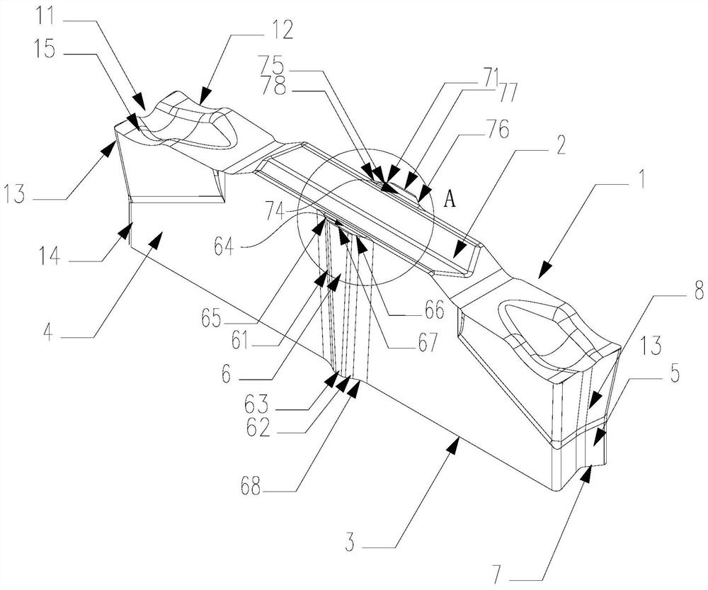
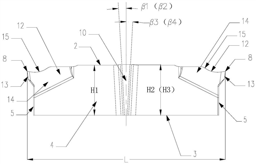
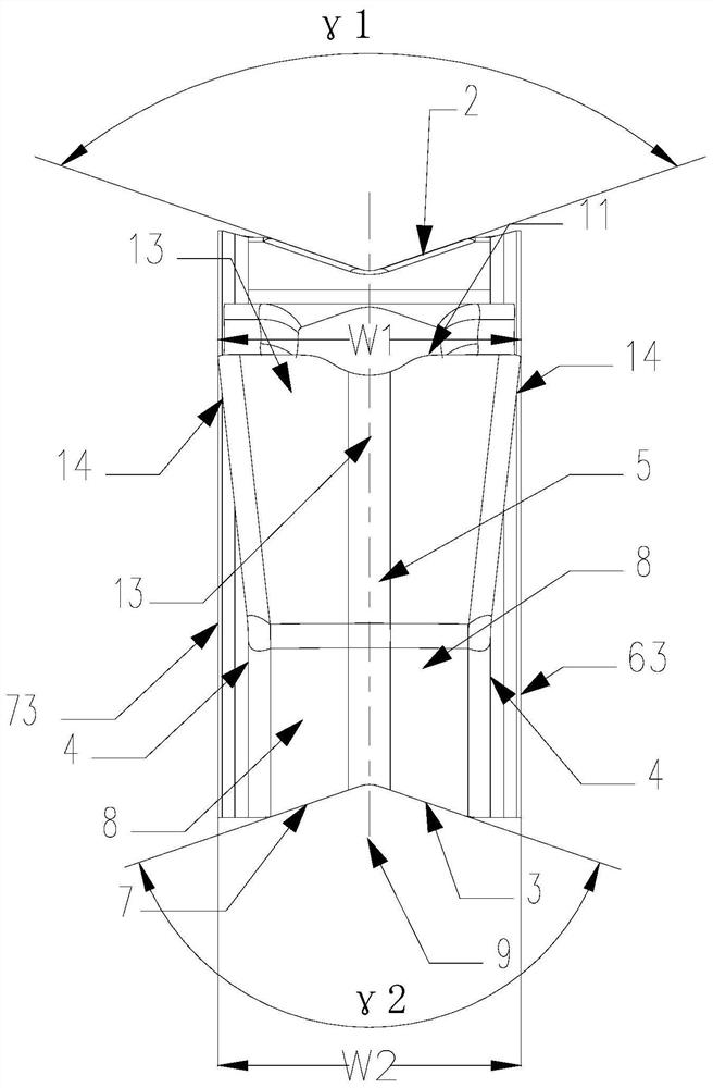
[0040] Such as Figure 1 to Figure 4As shown, in the grooving blade of this embodiment, the blade 1 includes an upper positioning surface 2, a lower positioning surface 3, two side surfaces 4 and two end surfaces 5, and a main cutting unit 8 is respectively provided at both ends of the blade 1, and the main cutting unit 8 is located at the intersection of the upper positioning surface 2 and the end surface 5, the main cutting unit 8 extends to the side 4, one of the side 4 is provided with the first cutting unit 6 for auxiliary cutting, and the other side 4 is provided with the first cutting unit 6 for auxiliary cutting The second cutting unit 7. In this embodiment, the blade 1 has two main cutting units 8 as an example, the two main cutting units 8 are symmetrical about the mid-end plane 10 of the center area of the two end faces 5, and the two main cutting units 8 are about the center of the two side faces 4 The lateral median plane 9 is symmetrical.
[0041] In this emb...
Embodiment 2
[0049] The grooving blade of this embodiment is basically the same as that of Embodiment 1, the only difference being:
[0050] In this embodiment, the first side surface 63 is a convex cylindrical surface, the first front cutting edge 65 and the first rear cutting edge 66 form a triangular structure on the upper positioning surface 2, and the first side cutting edge 67 is positioned on the upper positioning surface. An arc-shaped structure is formed on the surface 2.
[0051] Similarly, the second side surface 73 is a convex cylindrical surface, and the second front cutting edge 75 and the second rear cutting edge 76 form a triangular structure on the upper positioning surface 2, and the second side cutting edge 77 is positioned on the upper positioning surface. An arc-shaped structure is formed on the surface 2.
[0052] In the groove processing blade of this embodiment, the first cutting unit 6 and the second cutting unit 7 perform secondary cutting and surface finishing o...
Embodiment 3
[0054] Such as Figure 5 to Figure 7 As shown, the grooving blade of this embodiment is basically the same as that of Embodiment 1, the only difference being:
[0055] In this embodiment, only one end of the blade 1 has the main cutting unit 8 . The grooving blade of this embodiment can only be installed once and used, and other effects are equal to those of Embodiment 1.
[0056] In this embodiment, in the direction of the side surface 4, the distance between the main cutting unit 8 and the other end surface 5 (the end opposite to the main cutting unit 8) is L, and the maximum cutting length of the first cutting unit 6 and the second cutting unit 7 is L2 and L3, in order to improve the feed efficiency and cutting life of the insert 1, should satisfy: L2=L3=0.25L.
PUM
 Abstract
Description
Claims
Application Information
 - R&D
- Intellectual Property
- Life Sciences
- Materials
- Tech Scout
- Unparalleled Data Quality
- Higher Quality Content
- 60% Fewer Hallucinations
Browse by: Latest US Patents, China's latest patents, Technical Efficacy Thesaurus, Application Domain, Technology Topic, Popular Technical Reports.
© 2025 PatSnap. All rights reserved.Legal|Privacy policy|Modern Slavery Act Transparency Statement|Sitemap|About US| Contact US: help@patsnap.com


