
Groove machining blade with double cutting units and cutting tool

A groove machining and double cutting technology, applied in the field of metal cutting, can solve the problems of low cutting efficiency, large cutting depth, poor positioning rigidity, etc., and achieve the effect of improving cutting efficiency and life, improving surface quality and improving cutting rigidity.

Active Publication Date: 2019-09-20
ZHUZHOU CEMENTED CARBIDE CUTTING TOOLS CO LTD
View PDF7 Cites 0 Cited by
  • Summary
  • Abstract
  • Description
  • Claims
  • Application Information

AI Technical Summary

Problems solved by technology

This type of grooving insert with two cutting units generally forms the positioning structure of the insert through the upper, lower surface and end surface, and the upper and lower surfaces are arranged in parallel, and the upper surface can only be clamped by fasteners. Due to the existence of parts, this type of insert can only be used for shallow groove processing, and it is basically impossible to apply it to deep groove processing. Generally, deep groove processing can only be done by clamping the blade with an elastic clamping blade, thereby eliminating the need for fasteners. The impact on the depth of grooving, in order to maintain stable clamping, this type of grooving insert generally only has one cutting unit, and the cost performance is low
[0003] At the same time, the grooving process generally has the characteristics of large cutting depth and narrow grooving width, so the slit positioning platform for clamping the blade is generally thin, especially when the blade is overhanging long, the positioning rigidity is poor, and the cutting is prone to cutting vibration. In order to reduce vibration, ensure normal cutting of grooving inserts and maintain surface quality, the feed is usually reduced, resulting in low cutting efficiency

Method used


Image

  • Groove machining blade with double cutting units and cutting tool
  • Groove machining blade with double cutting units and cutting tool
  • Groove machining blade with double cutting units and cutting tool

Examples


Embodiment 1

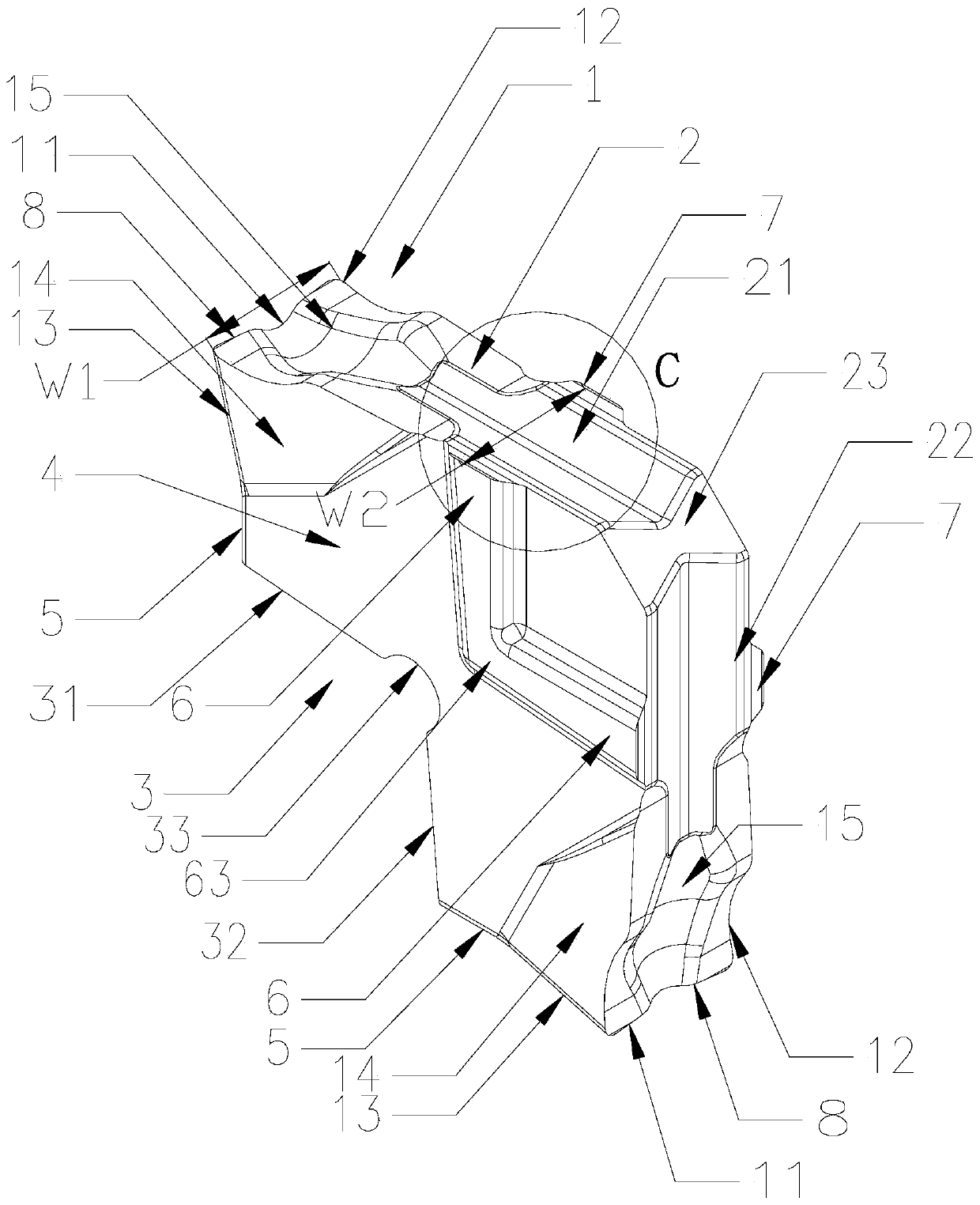
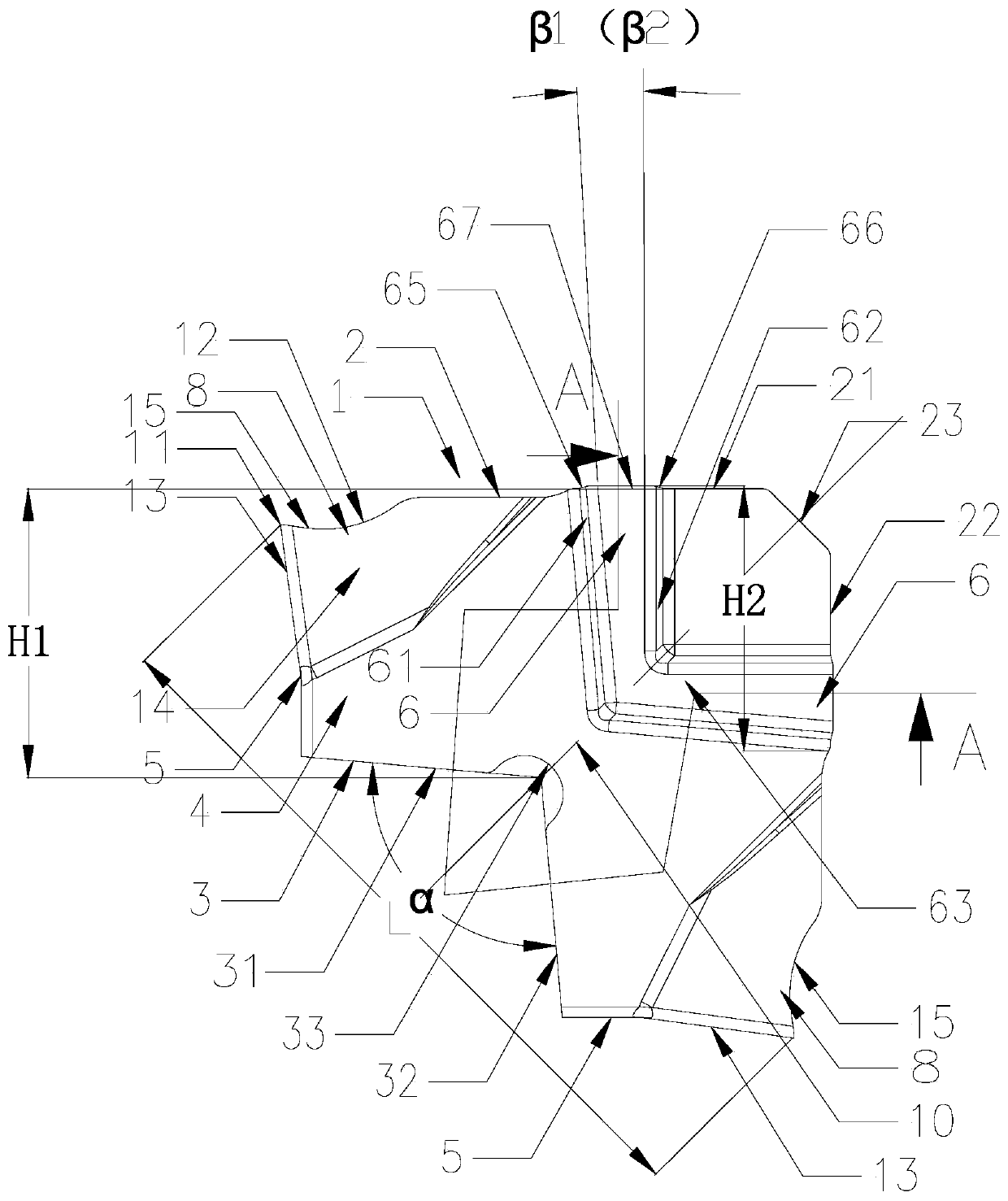
[0041] Such as Figure 1 to Figure 4 As shown, in the grooving insert with double cutting units in this embodiment, the insert 1 includes an upper surface 2, a lower surface 3, two side surfaces 4 and two end surfaces 5 connecting the upper and lower surfaces, the upper surface 2, the lower surface 3 Symmetrical about the mid-side plane 9 at the center of the two side surfaces 4, the upper surface 2 includes an upper horizontal positioning surface 21, an upper vertical positioning surface 22 and an upper transition surface 23 between the upper horizontal positioning surface 21 and the upper vertical positioning surface 22, and the lower surface 3. It is composed of the lower horizontal positioning surface 31, the lower vertical positioning surface 32 and the lower transition surface 33 between the lower horizontal positioning surface 31 and the lower vertical positioning surface 32. Between the upper horizontal positioning surface 21 and an end surface 5, the upper vertical pos...

Embodiment 2

[0054] Such as Figures 5 to 8 As shown, the groove machining insert with double cutting units of this embodiment is basically the same as that of Embodiment 1, the only difference being:

[0055] In this embodiment, one first cutting unit 6 and one second cutting unit 7 are respectively provided, the first cutting unit 6 is symmetrical about the mid-end plane 10 , and the second cutting unit 7 is symmetrical about the mid-end plane 10 .

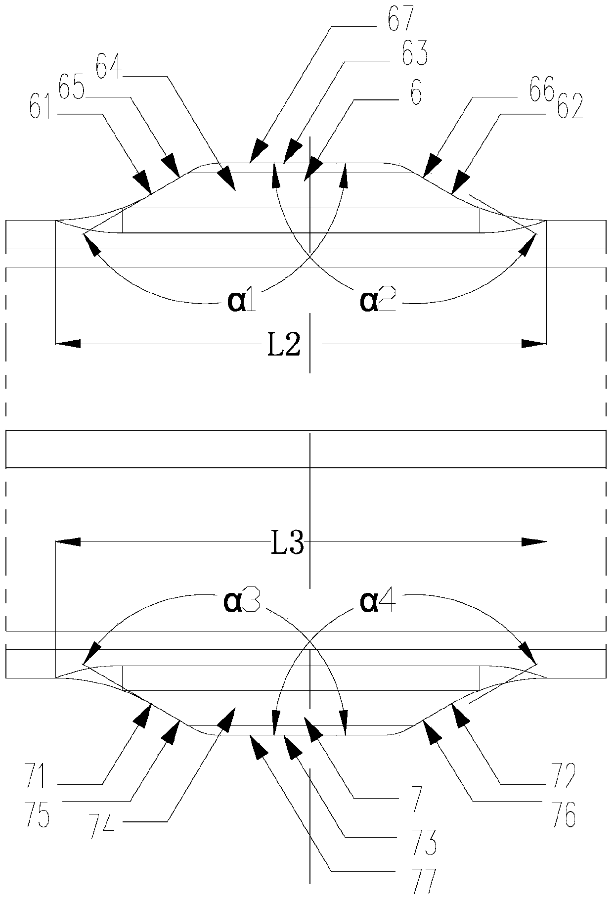
[0056]In this embodiment, the first cutting unit 6 includes a first front end surface 61, a first rear end surface 62 and a first side surface 63, and the first side surface 63 intersects with the first front end surface 61 and the first rear end surface 62 to form a first front side The cutting edge 68 and the first rear side cutting edge 69, the second cutting unit 7 includes a second front end surface 71, a second rear end surface 72 and a second side surface 73, the second side surface 73 and the second front end surface 71 and the secon...

Embodiment 3

[0063] Such as Figure 9 As shown, the cutting tool of this embodiment includes a cutter body 16, and the cutter body 16 is provided with a sipe 17. The cutting tool also includes the grooving blade in the above-mentioned embodiment 1, and the sipe 17 includes a groove end positioning surface 171, a groove front The side positioning surface 172 and the groove rear side positioning surface 173, the groove end positioning surface 171 can be positioned and matched with the lower horizontal positioning surface 31 or the lower vertical positioning surface 32, and the groove front side positioning surface 172 can be positioned with the lower horizontal positioning surface 31 or the lower vertical positioning surface. The positioning surface 32 is matched, and the positioning surface 173 on the rear side of the groove can be positioned and matched with the upper horizontal positioning surface 21 or the upper vertical positioning surface 22, and the blade 1 is elastically clamped in th...


PUM


Abstract

The invention discloses a groove machining blade with double cutting units and a cutting tool. The blade comprises an upper surface, a lower surface, two side surfaces and two end surfaces, wherein the two side surfaces are connected with the upper face and the lower surface, and the upper surface and the lower surface are symmetrical with respective to the side middle plane of the centers of the two side surfaces; the upper surface comprises an upper horizontal positioning surface, an upper vertical positioning surface and an upper transition surface positioned between the upper horizontal positioning surface and the upper vertical positioning surface, the lower surface is composed of a lower horizontal positioning surface, a lower vertical positioning surface and a lower transition surface positioned between the lower horizontal positioning surface and the lower vertical positioning surface; and a main cutting unit is arranged between the upper horizontal positioning surface and one end surface, and the main cutting unit is arranged between the upper vertical positioning surface and the other end surface, the two main cutting units are symmetrical with respective to the end middle plane in the center area of the two end surfaces, the upper horizontal positioning surface and the upper vertical positioning surface are symmetrical with respective to the end middle plane, the lower horizontal positioning surface and the lower vertical positioning surface are symmetric with respective to the end middle plane; and the cutter comprises the blade, the blade is elastically clamped in a cutter groove, other auxiliary fasteners are not needed, the installing and clamping is stable, and the cutter can be used twice.

Description

technical field [0001] The invention relates to the field of metal cutting, in particular to a grooving insert and a cutting tool with double cutting units. Background technique [0002] The positioning of the up and down direction of the grooving blade is realized by the upper and lower surfaces of the blade. The upper and lower surfaces of the blade are usually designed as a pair of concave surfaces, which cooperate with the corresponding convex positioning surfaces of the cutter body for the upper and lower grooving blades. Orientation. The slotting insert with double cutting unit mainly has a structure of double cutting part, which is installed twice and has good cost performance. This type of grooving insert with two cutting units generally forms the positioning structure of the insert through the upper, lower surface and end surface, and the upper and lower surfaces are arranged in parallel, and the upper surface can only be clamped by fasteners. Due to the existence...

Claims


Application Information

Patent Timeline
Patent Type & Authority Applications(China)
IPC IPC(8): B23C5/20
CPCB23C5/20
Inventor 江爱胜王社权汤爱民吴火飞文娟
Owner ZHUZHOU CEMENTED CARBIDE CUTTING TOOLS CO LTD
Learn More