Eureka AIR delivers breakthrough ideas for toughest innovation challenges, trusted by R&D personnel around the world.

Grinding device for improving sharpness of milling cutter

A sharpness and milling cutter technology, which is applied in the direction of grinding/polishing safety devices, milling cutters, milling machine equipment, etc., can solve the problems that affect the processing accuracy and processing efficiency of the workpiece, the processing accuracy requirements are low, and the sharpness is not as good as new knives. , to achieve a good cooling effect, reduce air pollution, and improve the effect of sharpness

Inactive Publication Date: 2019-09-10
SUZHOU MAIKAFU IND TECH CO LTD
View PDF0 Cites 3 Cited by
  • Summary
  • Abstract
  • Description
  • Claims
  • Application Information

AI Technical Summary

Problems solved by technology

[0003] After long-term use of the milling cutter, its cutting edge will become blunt due to wear and tear. After the cutting edge becomes blunt, it will affect the machining accuracy and processing efficiency of the workpiece.
At this time, the milling cutter needs to be replaced, and the replaced milling cutter will be discarded directly, which will cause a lot of waste. Most milling cutters can still be used after grinding
[0004] However, in fact, due to improper grinding, many milling cutters will find that their sharpness is far inferior to that of new knives after grinding and re-use, and can only be used for rough machining that requires low machining accuracy.

Method used


Image

  • Grinding device for improving sharpness of milling cutter
  • Grinding device for improving sharpness of milling cutter
  • Grinding device for improving sharpness of milling cutter

Examples


Embodiment 1

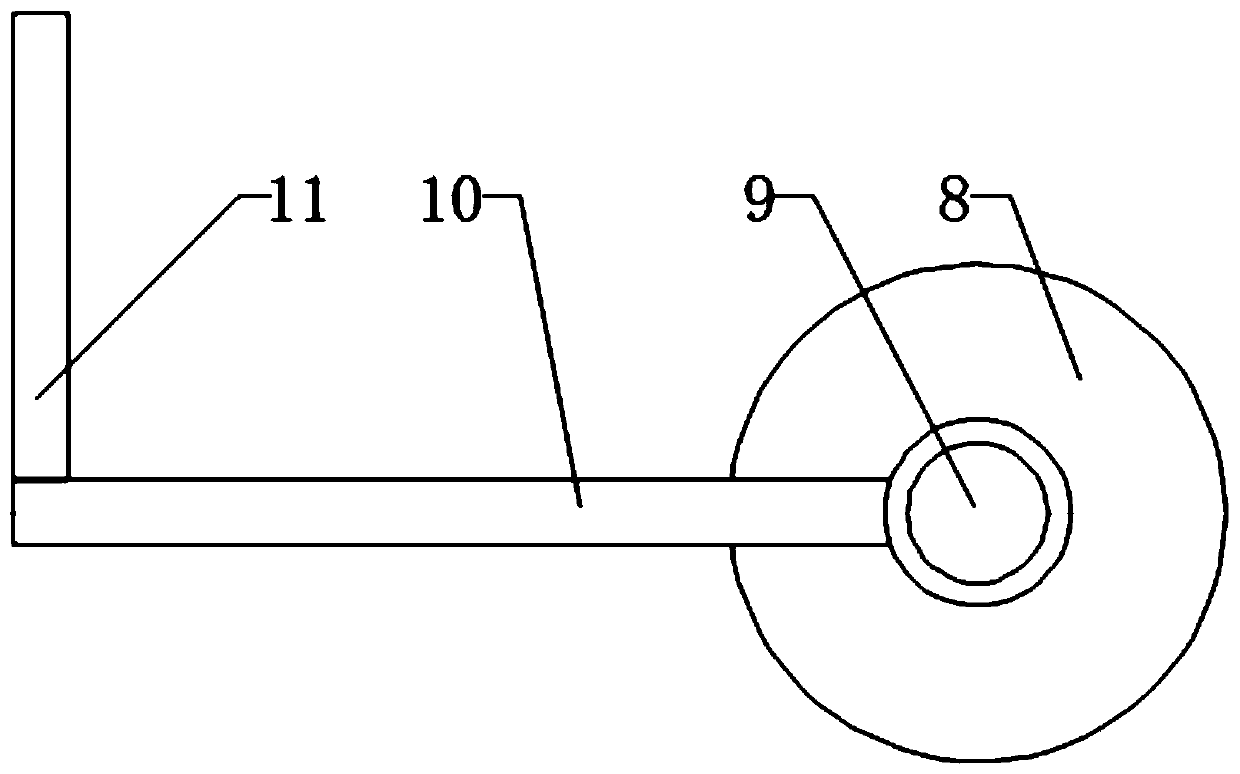
[0035] see Figure 1-2 , a grinding device based on improving the sharpness of the milling cutter, including a bottom plate 1, as an installation platform for the grinding device, a milling cutter synchronous rotator 2 is installed on one end of the bottom plate 1, and a milling cutter synchronous rotator 2 is installed on the top surface of the milling cutter synchronous rotator 2 The top mechanism 7, and the side of the milling cutter synchronous rotator 2 are equipped with a standard milling cutter 3 and a milling cutter 4 to be ground. One side of the knife 4 is provided with an air outlet 6 for blowing away grinding debris. Chips, the abrasive dust collection box 5 is fixed on the bottom plate 1, and a cylinder mounting plate 12 is fixedly installed on the side of the top mechanism 7, and a lifting cylinder 11 is installed below the cylinder mounting plate 12, and is fixed on the telescopic rod of the lifting cylinder 11. Connecting plate 10 is connected, and one end of ...


PUM


Abstract

The invention discloses a grinding device for improving sharpness of a milling cutter, and belongs to the field of industrial tools. The grinding device for improving the sharpness of the milling cutter comprises a bottom plate, wherein the bottom plate is used as a mounting platform of the grinding device. A milling cutter synchronous rotator is arranged at one end of the bottom plate, a top endmechanism is arranged on the top surface of the milling cutter synchronous rotator, and a standard milling cutter and a milling cutter to be milled are arranged on the side surface of the milling cutter synchronous rotator. According to the grinding device for improving the sharpness of the milling cutter, through the real-time comparison of the standard milling cutter, the grinding precision of the milling cutter to be milled is improved; an air outlet is formed in one side of the milling cutter to be milled and used for blowing away grinding scraps, wherein the air outlet is connected to thetop end mechanism, a scrap collecting box is arranged at the air outlet pointing position of the air outlet and is used for collecting the grinding scraps, and the scrap collecting box is fixed on the bottom plate; an air cylinder mounting plate is fixedly arranged on the side face of the top end mechanism, so that reasonable grinding can be realized, thus improving the sharpness of the wearing and blunt milling cutter, prolonging the service life of the milling cutter and reducing the waste of industrial cutters.

Description

technical field [0001] The invention relates to the field of industrial cutting tools, more specifically, to a grinding device based on improving the sharpness of milling cutters. Background technique [0002] A milling cutter is a rotating industrial tool with one or more teeth for milling operations. When working, each knife tooth cuts off the allowance of the workpiece intermittently in turn. Milling cutters are mainly used for machining planes, steps, grooves, forming surfaces and cutting off workpieces on milling machines. [0003] After long-term use of the milling cutter, its cutting edge will become blunt due to wear and tear. After the cutting edge becomes blunt, it will affect the machining accuracy and processing efficiency of the workpiece. At this time, it is necessary to replace the milling cutter, and discarding the replaced milling cutter directly will cause a large waste, and most milling cutters can still be used after being polished. [0004] However, i...

Claims


Application Information

Patent Timeline
IPC IPC(8): B24B3/02B24B55/06B24B55/02B24B55/12
CPCB24B3/02B24B55/02B24B55/06B24B55/12
Inventor 黄磊
Owner SUZHOU MAIKAFU IND TECH CO LTD
Why Eureka
Eureka Blog
Learn More